31
Caution You must have one power supply running at all times from each power supply zone and two power supplies from
each power supply zone to support redundancy. For setailed power sypply information about the Cisco ASR 1013
Router, see the Cisco ASR 1000 Series Aggregation Services Routers Hardware Installation Guide.
Caution Make certain that the chassis ground is connected before you begin removing and installing the power supply.
Follow these steps to remove power and the DC power supply from the chassis.
Step 1 Before servicing the power supply, switch the circuit breaker Off in your equipment area. As an additional precaution,
tape the circuit breaker switch in the Off position.
Step 2 Slip
on the ESD-preventative wrist strap that was included in the accessory kit.
Step 3 Switch the power supply circuit br
eaker switch to Off (O).
Step 4 Locate the ter
minal block on the rear of the chassis on the power supply.
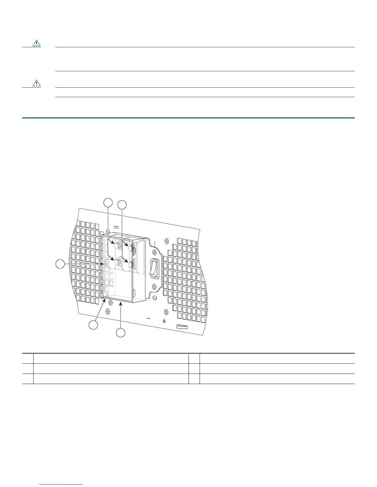
Figure 12 shows the DC power supply terminal block.
Figure 12 DC Power Supply Terminal Block
This unit might have more than one power supply connection. All connections must be remov
-48/-60V 40A
253914
3
4
5
1
2
1
Negative terminal
4
Plastic cover slotted area
2
Positive terminal
5
Terminal block plastic cover single screw
3
Terminal block plastic cover
Step 5 Rem
ove the slotted plastic cover from the terminal block (Figure 12). Loosen and remove the single screw on the plastic
cover. The plastic cover has slots that help to slid
e it out diagonally from the terminal block.
Step 6 Using
a nut driver (7/16 size), unsrew the positive kepnut, positive cable (Figure 13, callout 2) and the flat washer, in
that order. The terminal block houses two double-hole barrel lugs.

 Loading...


