4
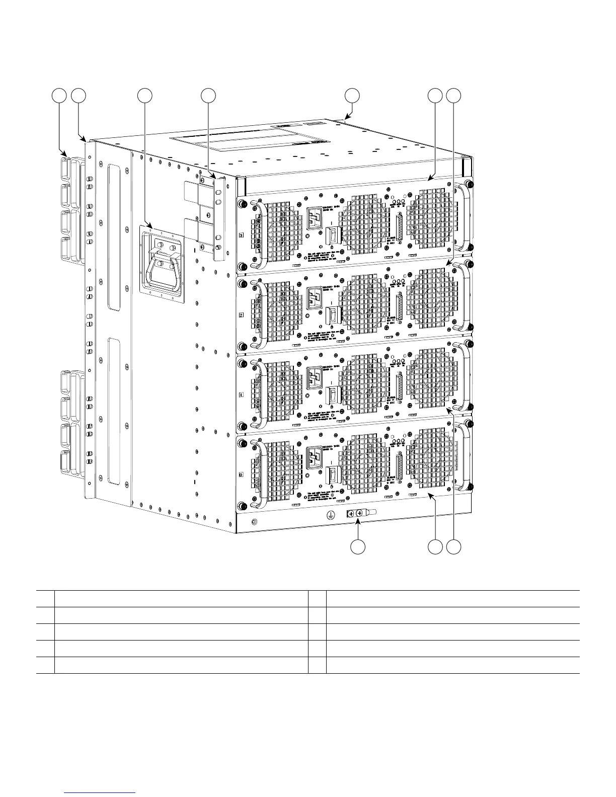
Figure 1 Cisco ASR 1013 Router Showing Front and Rear Rack-Mount Bracket Locations
9
2 5 6
8 7
431 2
207486
1
Cable management brackets
6
AC power supply in slot 2 (power supply zone 1)
2
Front rack-mount ears are shipped installed
7
AC power supply in slot 1 (power supply zone 0)
3
Chassis handle
8
AC power supply in slot 0 (power supply zone 0)
4
Rear rack-mount brackets
9
Chassis earth ground stud
5
AC power supply in slot 3 (power supply zone 1)
1
The two zones are split up with the numbering scheme: Zone 0 = PS0 and PS1 and for Zone 1 = PS2 and PS3.1.

 Loading...


