SignalJ2DirectionDescriptionSignalJ1
RTS
DTR
J2-C
J2-H
——>
——>
Twisted pair no.
4
O_RTS/CTS+
O_DTR/DSR+
J1-8
J1-7
CTS
DSR
J2-D
J2-E
<——
<——
Twisted pair no.
2
I_CTS/RTS+
I_DSR/DTR+
J1-11
J1-12
RLSD
GND
J2-F<——
—
Twisted pair no.
1
B_DSR/DTR+
GND
J1-6
J1-19
LT
GND
J2-K
J2-B
——>
—
Twisted pair no.
3
B_LL/LL+
GND
J1-13
J1-26
SD+
SD-
J2-P
J2-S
——>
——>
Twisted pair no.
5
O_TxC/RxD+
O_TxD/RxD-
J1-1
J1-14
RD+
RD-
J2-R
J2-T
<——
<——
Twisted pair no.
9
I_RxD/TxD+
I_RxD/TxD-
J1-5
J1-18
SCTE+
SCTE-
J2-U
J2-W
——>
——>
Twisted pair no.
6
O_TxCE/RxC+
O_TxCE/RxC-
J1-2
J1-15
SCR+
SCR-
J2-V
J2-X
<——
<——
Twisted pair no.
8
I_RxC/TxCE+
I_RxC/TxCE-
J1-4
J1-17
SCT+
SCT-
J2-Y
J2-AA
<——
<——
Twisted pair no.7B_TxC/TxC+
B_TxC/TxC-
J1-3
J1-16
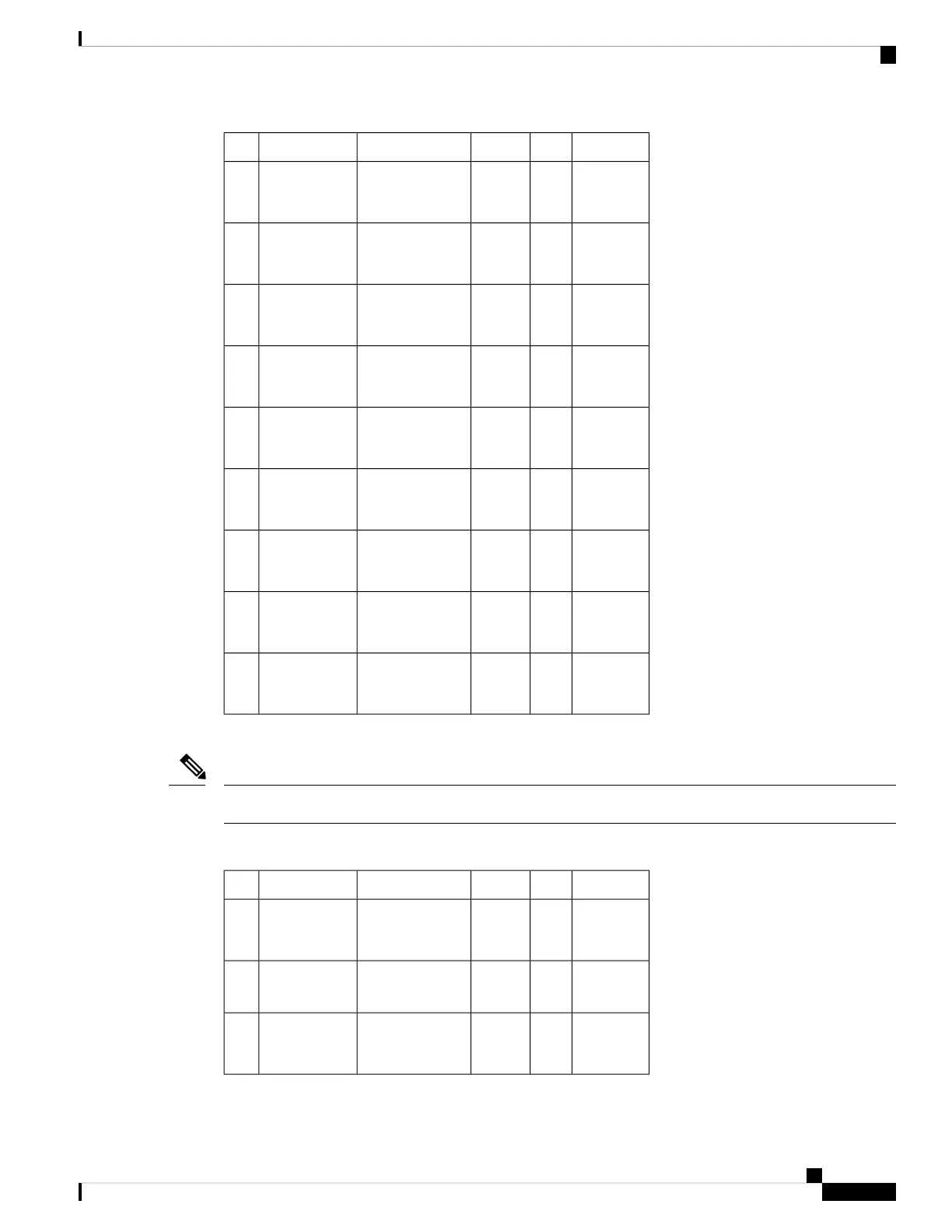
The following table lists the V.35 DCE cable pinouts. Arrows indicate signal direction.
Any pin not referenced is not connected.
Note
Table 53: V.35 DCE Cable Pinouts (34-Pin Female Connector)
SignalJ2DirectionDescriptionSignalJ1
---Local
connections
MODE_1
MODE_0
J1-22
J1-23
Shield
GND
J2-A—Shield--
RTS
DTR
J2-C
J2-H
<——
<——
Twisted pair no.
4
I_CTS/RTS+
I_DSR/DTR+
J1-11
J1-12
Cisco ASR 9000 Series Aggregation Services Router SIP and SPA Hardware Installation Guide
79
Overview: Cisco ASR 9000 Series Router Shared Port Adapters
4-Port Serial Interface SPA Cables, Connectors, and Pinouts
 Loading...


