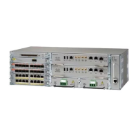
Only Pins 1, 2, 4, 6, and 8 are available for customer use. The remaining pins are for Cisco manufacturing
test, and should not be connected. Use a shielded cable for connection to this port for EMC protection. Table
B-21 on page B-28 summarizes the pinouts on the alarm port.
SUMMARY STEPS
1.
Attach an RJ-45 cable to the alarm port.
2.
Attach the other end of the RJ-45 cable to the relay controller.
DETAILED STEPS
Step 1
Attach an RJ-45 cable to the alarm port.
Step 2
Attach the other end of the RJ-45 cable to the relay controller.
For information about how to map alarm inputs to critical, major, and minor alarm conditions, see the Cisco ASR 903
Software Configuration Guide .
Cisco ASR 9000 Series Aggregation Services Router Satellite Systems Installation Guide
66
Installing the Cisco ASR 903 Router as a Satellite Shelf
Connecting the Fan Tray Alarm Port

 Loading...


