Chapter 1 Product Overview
Rear-Panel Description
1-18
Catalyst 2900 Series XL Hardware Installation Guide
78-6461-03
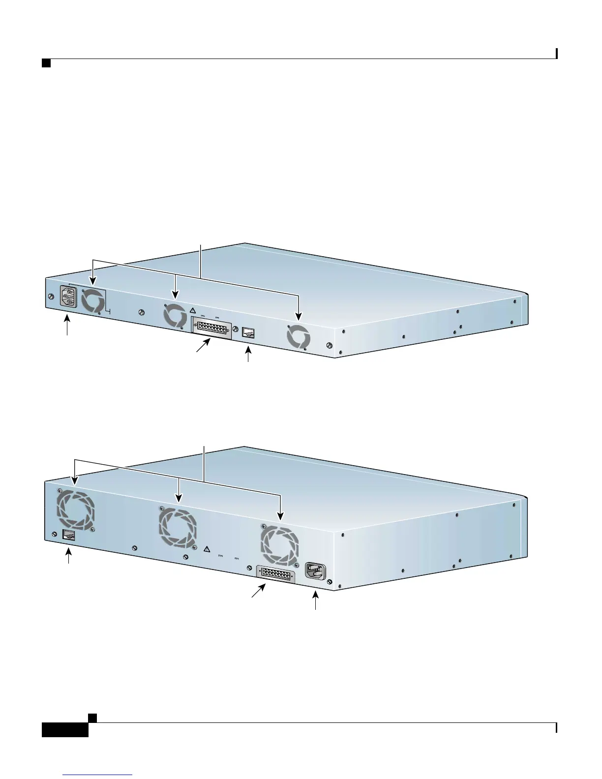
Rear-Panel Description
The switch rear panels have an AC power connector, an RPS connector, and an
RJ-45 console port (see Figure 1-10, Figure 1-10,andFigure 1-11), which are
described in this section.
Figure 1-9 Catalyst 2912 XL, 2924 XL, and 2924C XL Rear Panel
Figure 1-10 Catalyst 2924M XL and Catalyst 2912MF XL Rear Panel
R
A
T
I
N
G
1
0
0
-
1
2
7
/
2
0
0
-
2
4
0
V
~
1
.
0
A
/
O
.
5
A
5
0
-
8
0
H
Z
D
C
I
N
P
U
T
S
F
O
R
R
E
M
O
T
E
P
O
W
E
R
S
U
P
P
L
Y
S
P
E
C
I
F
I
E
D
I
N
M
A
N
U
A
L
+
5
V
@
9
A
,
+
1
2
V
@
0
.
5
A
C
O
N
S
O
L
E
Redundant
power system
connector
RJ-45
connector
AC power
connector
Fans
47295
AC power
connector
CONSOLE
DC INPUT
R
A
T
I
N
G
1
0
0
-
1
2
0
/
2
0
0
-
2
4
0
V
2
.
0
A
/
1
.
0
A
5
0
-
6
0
H
Z
~
D
C
I
N
P
U
T
S
F
O
R
R
E
M
O
T
E
P
O
W
E
R
S
U
P
P
L
Y
S
P
E
C
I
F
I
E
D
I
N
M
A
N
U
A
L
+
5
V
@
9
A
,
+
1
2
V
@
0
.
5
A
47296
Redundant
power system
connector
RJ-45
connector
Fans
 Loading...


