2-25
Catalyst 2900 Series XL Hardware Installation Guide
78-6461-03
Chapter 2 Installation
Powering On the Switch and Running POST
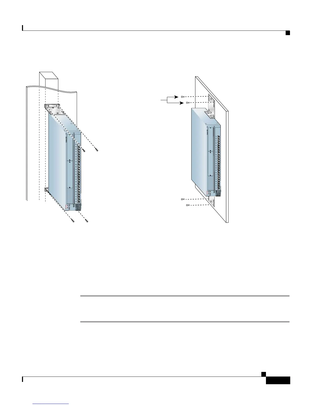
Figure 2-16 Mounting a Modular Switch to a Wall
After the switch is mounted on the wall, power the switch as described in
“Powering On the Switch and Running POST” sectiononpage2-25.
Powering On the Switch and Running POST
To power on the switch after you install it, follow these steps:
Step 1 Connect one end of the AC power cord to the AC power connector on the switch.
Step 2 Connect the other end of the power cord to an AC power outlet.
As the switch powers on, it begins POST, a series of eight tests that run
automatically to ensure that the switch functions properly. When the switch
begins POST, the port LEDs turn amber for 2 seconds, and then they turn green.
Vertical wall-mount
User-supplied
screws
Vertical
wall stud
M
O
D
E
1
x2
x
3
x
4
x
5
x6
x
7
x
8
x
9
x
1
0
x
1
1
x
1
2
x
1
3
x
1
4
x
1
5
x
1
6
x
1
7
x
1
8
x
1
9
x
2
0
x
2
1
x
2
2
x
2
3
x
2
4
x
S
E
R
IE
S
1
0
B
a
s
e
T
/
1
0
0
B
a
s
e
T
X
User-supplied
screws
Parallel wall-mount
47306
M
O
D
E
1
x
2
x
3
x
4
x5
x
6
x
7
x
8
x
9
x
1
0
x
1
1
x
1
2
x
1
3
x
1
4
x
1
5
x
1
6
x
1
7
x
1
8
x
1
9
x
2
0
x
2
1
x
2
2
x
2
3
x
2
4
x
S
E
R
IE
S
1
0
B
a
s
e
T
/
1
0
0
B
a
s
e
T
X
 Loading...


