B-5
Catalyst 2900 Series XL Hardware Installation Guide
78-6461-03
Appendix B Connectors and Cable Specifications
Cable and Adapter Specifications
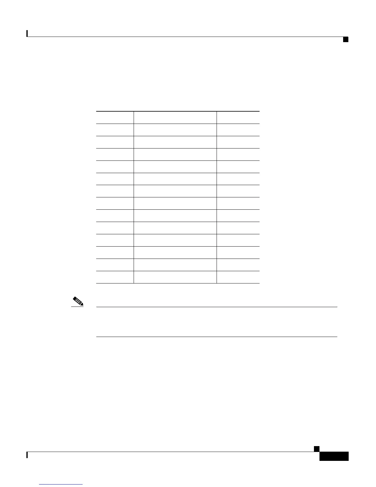
RJ-21 Cable Pinouts
Note Table B-1 shows the pinouts for the RJ-21 connector on a
Catalyst 2924 LRE XL switch. On a Catalyst 2912 LRE XL switch, only
circuits 1 to 12 are valid.
Console Port
The console port uses an 8-pin RJ-45 connector, as shown in Figure B-7 and
described in Table B-2. The supplied RJ-45-to-RJ-45 rollover cable and adapters
connect the console port of the switch to a console PC or terminal. The following
sections describe the rollover cable and adapters for the console port.
Table B-1 RJ-21 Cable Pinouts
Pins Circuit Pins Circuits
1, 26 1, tip/ring 14, 39 14, tip/ring
2, 27 2, tip/ring 15, 40 15, tip/ring
3, 28 3, tip/ring 16, 41 16, tip/ring
4, 29 4, tip/ring 17, 42 17, tip/ring
5, 30 5, tip/ring 18, 43 18, tip/ring
6, 31 6, tip/ring 19, 44 19, tip/ring
7, 32 7, tip/ring 20, 45 20, tip/ring
8, 33 8, tip/ring 21, 46 21, tip/ring
9, 34 9, tip/ring 22, 47 22, tip/ring
10, 35 10, tip/ring 23, 48 23, tip/ring
11, 36 11, tip/ring 24, 49 25, tip/ring
12, 37 12, tip/ring 25, 50 no connect
13, 38 13, tip/ring
 Loading...


