31-67
Catalyst 3550 Multilayer Switch Software Configuration Guide
78-11194-09
Chapter 31 Configuring IP Unicast Routing
Configuring Multi-VRF CE
This is the packet-forwarding process in a multi-VRF-CE-enabled network:
• When the switch receives a packet from a VPN, the switch looks up the routing table based on the
input policy label number. When a route is found, the switch forwards the packet to the PE.
• When the ingress PE receives a packet from the CE, it performs a VRF lookup. When a route is
found, the router adds a corresponding MPLS label to the packet and sends it to the MPLS network.
• When an egress PE receives a packet from the network, it strips the label and uses the label to
identify the correct VPN routing table. Then it performs the normal route lookup. When a route is
found, it forwards the packet to the correct adjacency.
• When a CE receives a packet from an egress PE, it uses the input policy label to look up the correct
VPN routing table. If a route is found, it forwards the packet within the VPN.
To configure VRF, you create a VRF table and specify the Layer 3 interface associated with the VRF.
Then configure the routing protocols in the VPN and between the CE and the PE. BGP is the preferred
routing protocol used to distribute VPN routing information across the provider’s backbone. The
multi-VRF CE network has three major components:
• VPN route target communities—lists of all other members of a VPN community. You need to
configure VPN route targets for each VPN community member.
• Multiprotocol BGP peering of VPN community PE routers—propagates VRF reachability
information to all members of a VPN community. You need to configure BGP peering in all PE
routers within a VPN community.
• VPN forwarding—transports all traffic between all VPN community members across a VPN
service-provider network.
Default Multi-VRF CE Configuration
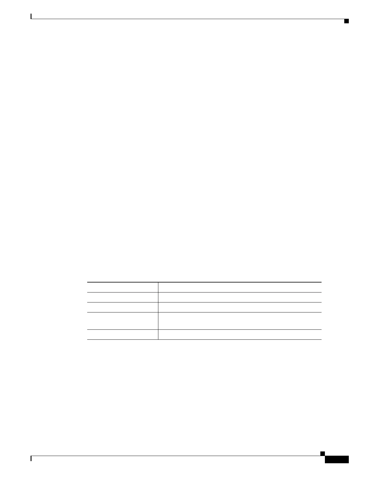
Table 31-14 shows the default VRF configuration.
Table 31-14 Default VRF Configuration
Feature Default Setting
VRF Disabled. No VRFs are defined.
Maps No import maps, export maps, or route maps are defined.
VRF maximum routes Fast Ethernet switches: 8000
Gigabit Ethernet switches: 12000.
Forwarding table The default for an interface is the global routing table.

 Loading...

