EasyManuals Logo

Cisco Catalyst 3560-CX User Manual

Cisco Catalyst 3560-CX
88 pages
To Next Page IconTo Next Page
To Previous Page IconTo Previous Page
Page #37 background imageLoading...
Page #37 background image
Step 2
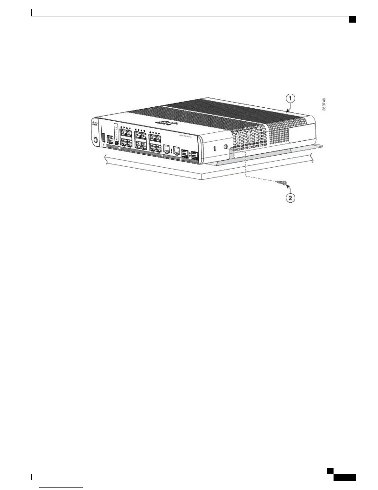
Use the two number-10 Phillips pan-head screws to secure the mounting tray to the switch.
Figure 19: Securing the Mounting Tray to the Switch
Step 3
Place one side of the magnet against the bottom of the mounting tray. Mount the magnet and switch on a metal wall.
Read the wall-mounting instructions carefully before beginning installation. Failure to use the correct hardware or to
follow the correct procedures could result in a hazardous situation to people and damage to the system. Statement 378
Catalyst 3560-CX and 2960-CX Switch Hardware Installation Guide
27
Switch Installation
With a Mounting Tray

Table of Contents

Other manuals for Cisco Catalyst 3560-CX

Questions and Answers:

Question and Answer IconNeed help?

Do you have a question about the Cisco Catalyst 3560-CX and is the answer not in the manual?

Cisco Catalyst 3560-CX Specifications

General IconGeneral
ModelWS-C3560CX-8PC-S
Switching Capacity20 Gbps
Product TypeSwitch
ManageableYes
Layer SupportedLayer 3
Jumbo Frame SupportYes
Jumbo Frame Size9198 bytes
Input Voltage100 - 240 VAC
Operating Temperature32 to 113°F (0 to 45°C)
Power SupplyInternal
Ports8 x 10/100/1000 Ethernet Ports
Uplink Ports2 x 1G SFP
PoEPoE+
Form FactorDesktop, Wall-mountable
MAC Address Table Size16, 000 entries
Power SourceAC

Related product manuals