1-26
Catalyst 3650 Switch Hardware Installation Guide
OL-29734-01
Chapter 1 Product Overview
Front Panel
• Two uplink port LEDs labeled TE1, TE2—This labeling represents two slots supporting SFP and
SFP+ modules.
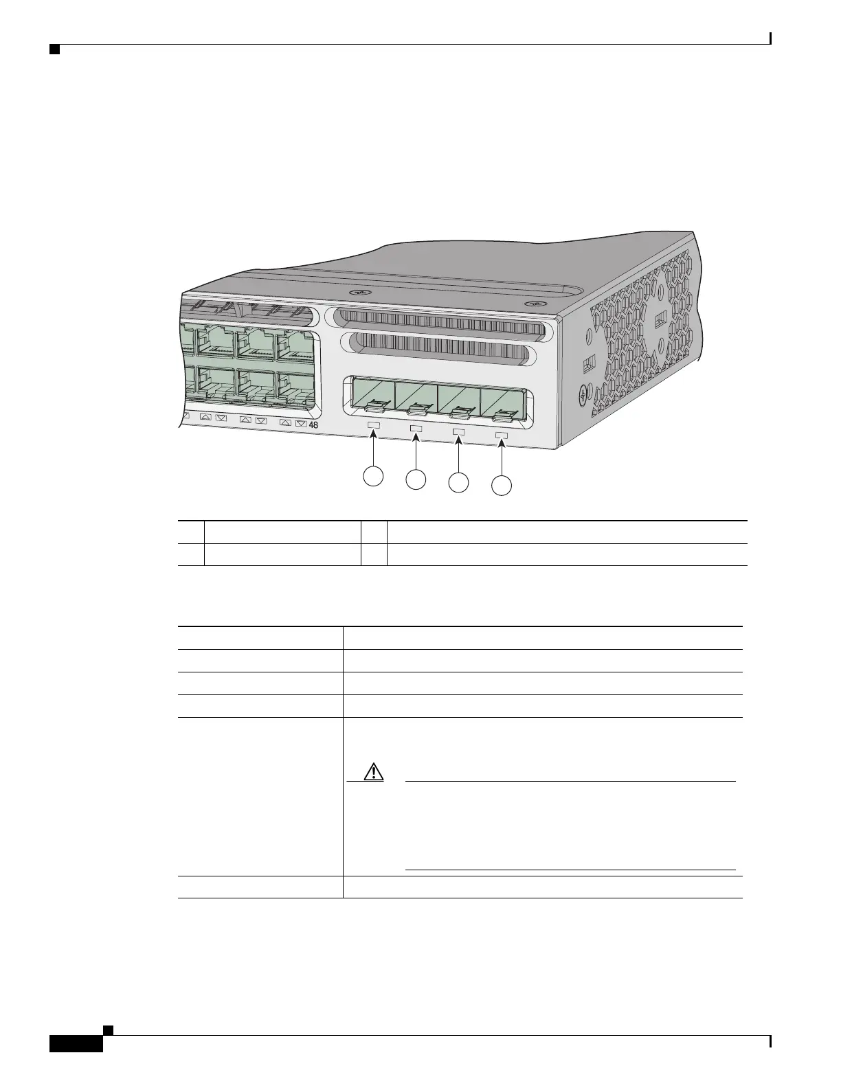
Figure 1-11 shows an example of an uplink port LED arrangement representing two SFP and two SFP+
ports (Catalyst 3650-48FD-S switch model).
Figure 1-11 Uplink port LED
Figure 1-12 shows an example of an uplink port LED arrangement representing QSFP+ ports (Catalyst
3650-12X48UZ-X switch models).
1 G1 LED 3 G3, TE3 LED
2 G2 LED 4 G4, TE4 LED
Table 1-9 Uplink Port LEDs
Color Uplink Port Link Status
Off Link is off.
Green Link is on, no activity.
Blinking green Activity on a link, no faults.
Blinking amber Link is off due to a fault or because it has exceeded a limit set in the
switch software.
Caution Link faults occur when noncompliant cabling is connected
to an SFP or SFP+ port. Use only standards-compliant
cabling to connect to Cisco SFP and SFP+ ports. You must
remove any cable or device from the ports if they cause a
link fault.
Amber Link for the SFP or SFP+ has been disabled.
Catalyst 3650 48PoE+ 2X10G
TE3
G1
G2
G3
G4
TE4
347665
1
2
3
4

 Loading...


