Follow the grounding procedure instructions, and use a UL-listed lug (included in the accessory kit).
Caution
To comply with the Telcordia GR-1089 NEBS standard for electromagnetic compatibility and safety, connect
the (Management Ethernet) ports only to intra-building or unexposed wiring or cable. The intrabuilding cable
must be shielded and the shield must be grounded at both ends. The intra-building port(s) of the equipment
or subassembly must not be metallically connected to interfaces that connect to the OSP or its wiring. These
interfaces are designed for use as intra-building interfaces only (Type 2 or Type 4 ports as described in
GR-1089-CORE) and require isolation from the exposed OSP cabling. The addition of Primary Protectors is
not sufficient protection in order to connect these interfaces metallically to OSP wiring.
Caution
Procedure
Step 1 Use the ground lug screw and the lug ring for a single-ground connection. Use the dual-hole lug for a ground
connection in a NEBS installation.
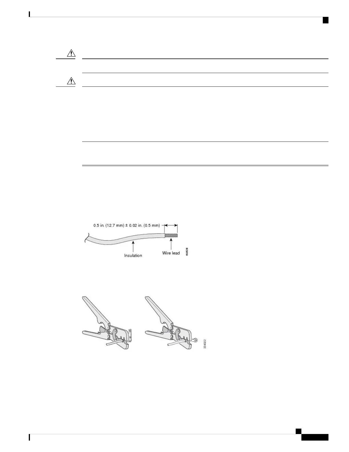
Step 2 Strip the 12-gauge or 8-gauge ground wire to 0.5 inch (12.7 mm) ± 0.02 inch (0.5 mm). Stripping more than
the recommended amount of wire can leave exposed wire from the connector. Use 12-gauge copper ground
wire for the single-ground connection. Use 8-gauge copper ground wire for the dual-ground connection.
Figure 54: Stripping the Ground Wire
Step 3 Slide the open end of the ground lug over the exposed area of the wire.
Step 4 Using a Panduit crimping tool, crimp the ground lug to the wire.
Figure 55: Crimping the Ground Lug
Step 5 Use the ground screw to attach the single-ground lug to the switch rear panel. Use two ground screws to attach
the dual-hole lug to the switch rear panel.
Catalyst 3850 Switch Hardware Installation Guide
77OL-26779-05
Power Supply Installation
Grounding the Switch