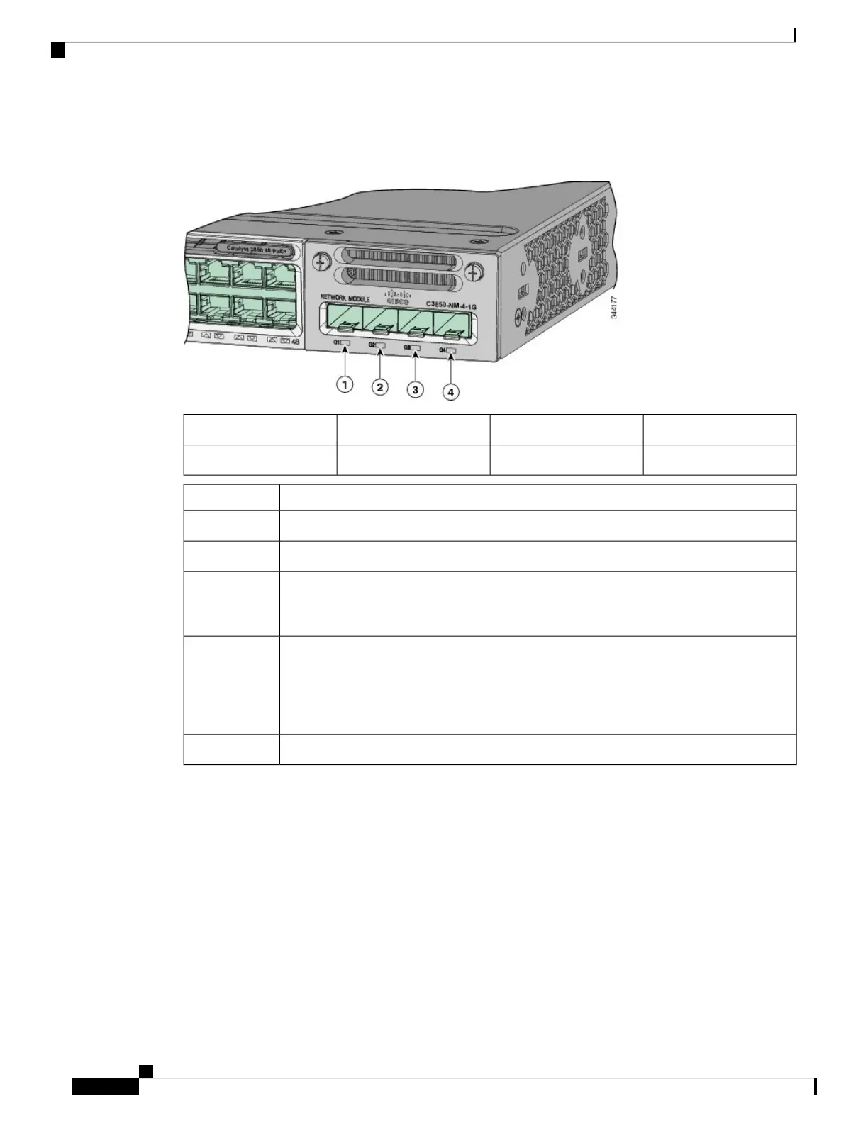
Network Module LEDs
Figure 10: Network Module LEDs
G3 LED3G1 LED1
G4 LED4G2 LED2
Network Module Link StatusColor
Link is off.Off
Link is on; no activity.Green
Activity on a link; no faults.
The LED will blink green even when there is very little control traffic.
Note
Blinking green
Link is off due to a fault or because it has exceeded a limit set in the switch software.
Link faults occur when noncompliant cabling is connected to an SFP/SFP+ port.
Use only standard-compliant cabling to connect to Cisco SFP/SFP+ ports. You
must remove from the network any cable or device that causes a link fault.
Caution
Blinking amber
Link for the SFP/SFP+ has been disabled.Amber
Rear Panel
The switch rear panel includes StackWise connectors, StackPower or XPS 2200 connectors, ports, fan modules,
and power supply modules.
Catalyst 3850 Switch Hardware Installation Guide
OL-26779-0522
Product Overview
Network Module LEDs