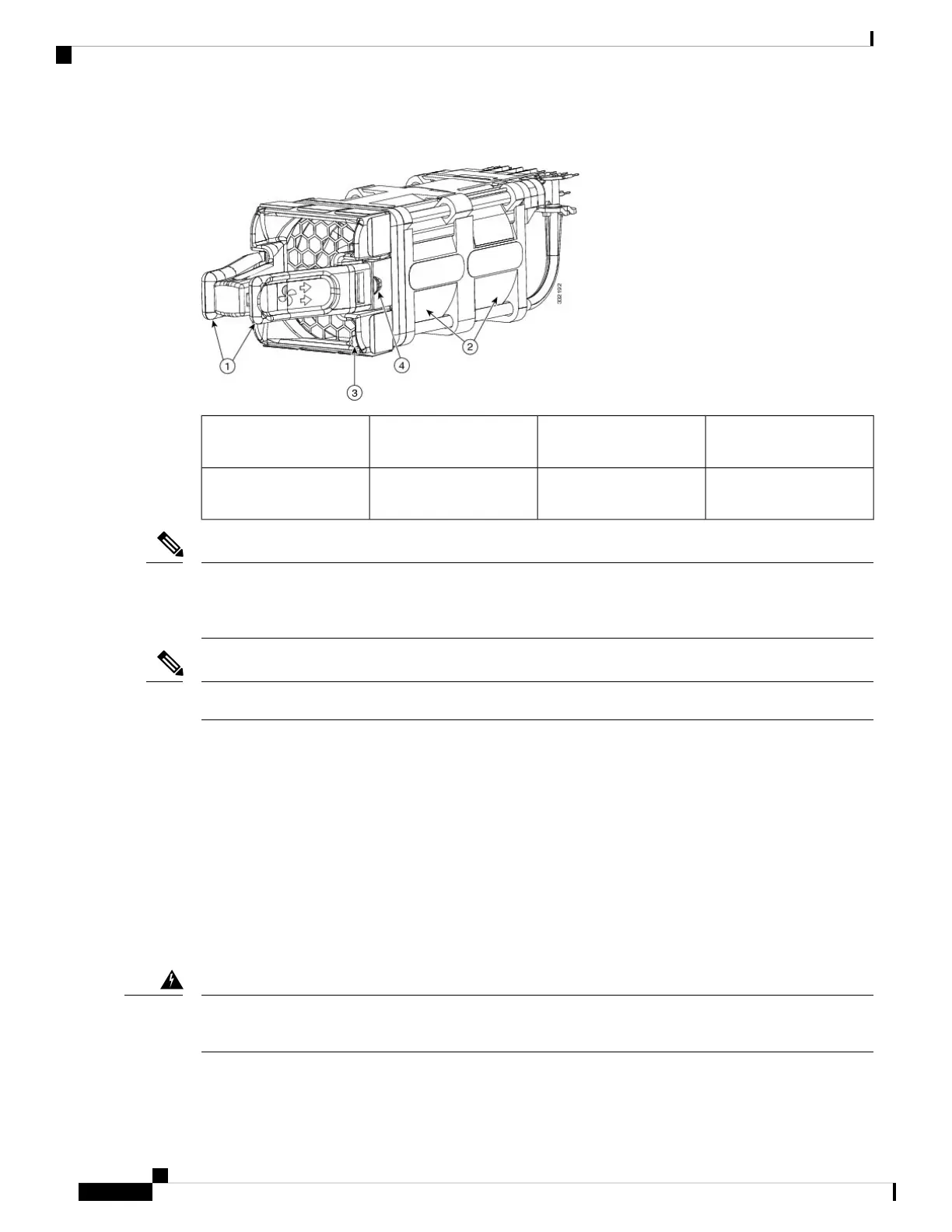
Figure 68: Fan Module for Catalyst WS-C3850-48XS Switch Models
Fan status LED
(red/green)
3Fan assembly levers1
Fan assembly retention
latch
4Fans2
Ensure that the power supplies are inserted correctly to match the corresponding fans. Power supplies with
blue handles correspond to fans with blue handles, and power supplies with red handles correspond to fans
with red handles.
Note
The WS-C3850-48XS switches require five fans for proper cooling.
Note
Installation Guidelines
Observe these guidelines when removing or installing a fan module:
• Do not force the fan module into the slot. This can damage the pins on the switch if they are not aligned
with the module.
• A fan module that is only partially connected to the switch can disrupt the system operation.
• The switch supports hot swapping of the fan module. You can remove and replace the module without
interrupting normal switch operation.
Only trained and qualified personnel should be allowed to install, replace, or service this equipment. Statement
1030
Warning
Catalyst 3850 Switch Hardware Installation Guide
OL-26779-0584
Installing the Fan
Installation Guidelines