EasyManuals Logo

Cisco Catalyst C9200-48T User Manual

Cisco Catalyst C9200-48T
94 pages
To Next Page IconTo Next Page
To Previous Page IconTo Previous Page
Page #48 background imageLoading...
Page #48 background image
All the switches ship with a blank cover in the second power supply slot if the switches are ordered with only
one power supply module.
For information about available PoE and PoE+ requirements, see these sections the Power Supply Modules,
on page 9.
The power supply modules are autoranging units that support input voltages between 100 and 240 VAC. Each
AC power supply module has a power cord for connection to an AC power outlet. The modules use an 18-AWG
power cord.
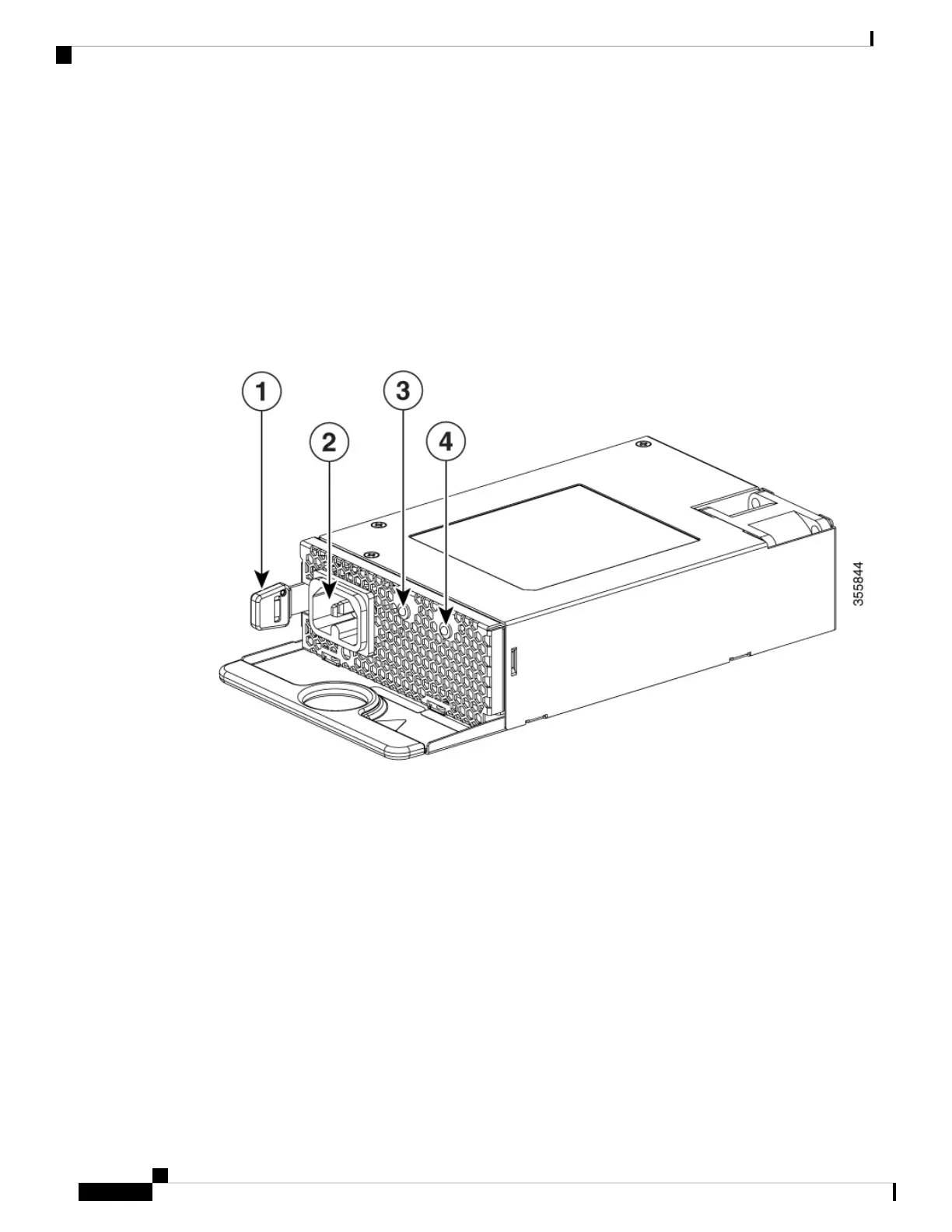
The following illustrations show the power supply modules.
Figure 26: 1000W AC Power Supply
Cisco Catalyst 9200 Series Switches Hardware Installation Guide
42
Installing a Power Supply Unit
Power Supply Modules Overview

Table of Contents

Questions and Answers:

Question and Answer IconNeed help?

Do you have a question about the Cisco Catalyst C9200-48T and is the answer not in the manual?

Cisco Catalyst C9200-48T Specifications

General IconGeneral
Total 10/100/1000 or Multigigabit copper ports48 x 10/100/1000
Switching Capacity176 Gbps
DRAM4 GB
Flash16 GB
PoE SupportNo
MTBF1, 000, 000 hours
Power DeviceInternal power supply
Rack MountableYes
Product TypeLayer 3 Switch
Uplink Ports4 x 10 Gigabit Ethernet
Input VoltageAC 120/230 V
Authentication MethodSecure Shell (SSH), RADIUS, TACACS+
Operating Temperature0 to 45°C

Related product manuals