EasyManuals Logo

Cisco Catalyst C9200-48T User Manual

Cisco Catalyst C9200-48T
94 pages
To Next Page IconTo Next Page
To Previous Page IconTo Previous Page
Page #55 background imageLoading...
Page #55 background image
CHAPTER 5
Installing a Fan Module
Fan Modules Overview , on page 49
Installation Guidelines, on page 50
Installing a Fan Module, on page 50
Finding the Fan Module Serial Number, on page 51
Fan Modules Overview
Cisco Catalyst 9200 (C9200) Series switches support two field-replaceable fan modules providing N+1
redundancy support. The switch should be able to operate at ambient temperature if one of the fans fails.
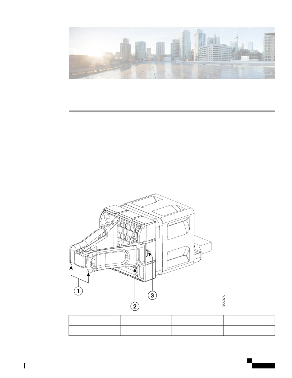
Figure 32: Fan Module
Retainer clip3Extraction handles1
Fan LED2
Cisco Catalyst 9200 Series Switches Hardware Installation Guide
49

Table of Contents

Questions and Answers:

Question and Answer IconNeed help?

Do you have a question about the Cisco Catalyst C9200-48T and is the answer not in the manual?

Cisco Catalyst C9200-48T Specifications

General IconGeneral
Total 10/100/1000 or Multigigabit copper ports48 x 10/100/1000
Switching Capacity176 Gbps
DRAM4 GB
Flash16 GB
PoE SupportNo
MTBF1, 000, 000 hours
Power DeviceInternal power supply
Rack MountableYes
Product TypeLayer 3 Switch
Uplink Ports4 x 10 Gigabit Ethernet
Input VoltageAC 120/230 V
Authentication MethodSecure Shell (SSH), RADIUS, TACACS+
Operating Temperature0 to 45°C

Related product manuals