EasyManuals Logo

Cisco Catalyst C9200-48T User Manual

Cisco Catalyst C9200-48T
94 pages
To Next Page IconTo Next Page
To Previous Page IconTo Previous Page
Page #86 background imageLoading...
Page #86 background image
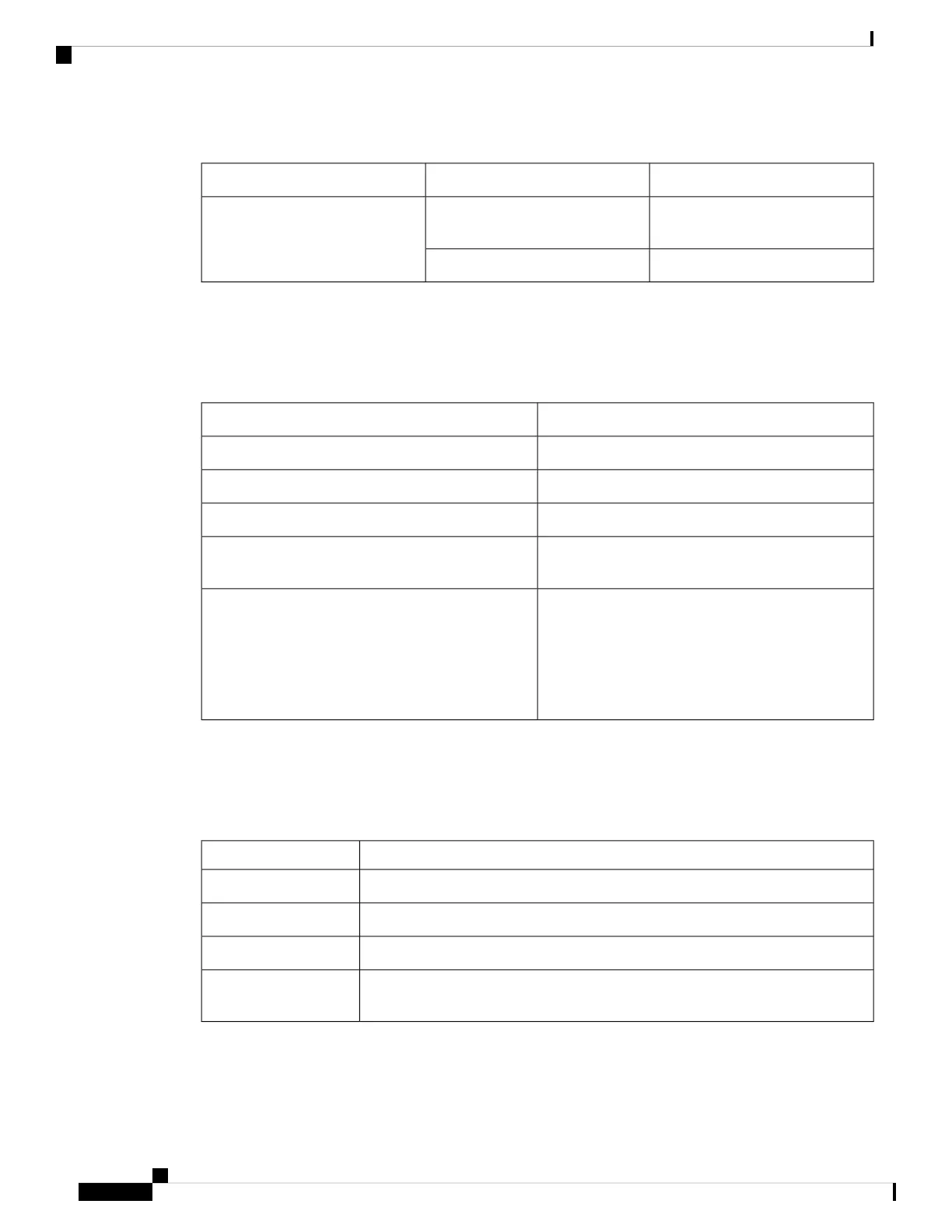
Table 22: Console LED
DescriptionColorLED
USB Mini-Type B console port is
active.
Solid greenConsole
USB cable not connectedOff
System LED
Table 23: System LED
System StatusColor
System is not powered on.Off
System is operating normally.Green
System is loading the software.Blinking green
System is receiving power but is not functioning
properly.
Amber
There is a fault with one of the following:
Network module (non traffic-related)
Power supply
Fan module
Blinking amber
MASTER LED
Table 24: MASTER LED
DescriptionColor
Switch is not the master switch.Off
Switch is the stack master or a standalone switch.Green
Switch is in stack standby mode.Fast blinking green
An error occurred when the switch was selecting the stack master switch, or another
type of stack error occurred.
Amber
Cisco Catalyst 9200 Series Switches Hardware Installation Guide
80
Switch LEDs
System LED

Table of Contents

Questions and Answers:

Question and Answer IconNeed help?

Do you have a question about the Cisco Catalyst C9200-48T and is the answer not in the manual?

Cisco Catalyst C9200-48T Specifications

General IconGeneral
Total 10/100/1000 or Multigigabit copper ports48 x 10/100/1000
Switching Capacity176 Gbps
DRAM4 GB
Flash16 GB
PoE SupportNo
MTBF1, 000, 000 hours
Power DeviceInternal power supply
Rack MountableYes
Product TypeLayer 3 Switch
Uplink Ports4 x 10 Gigabit Ethernet
Input VoltageAC 120/230 V
Authentication MethodSecure Shell (SSH), RADIUS, TACACS+
Operating Temperature0 to 45°C

Related product manuals