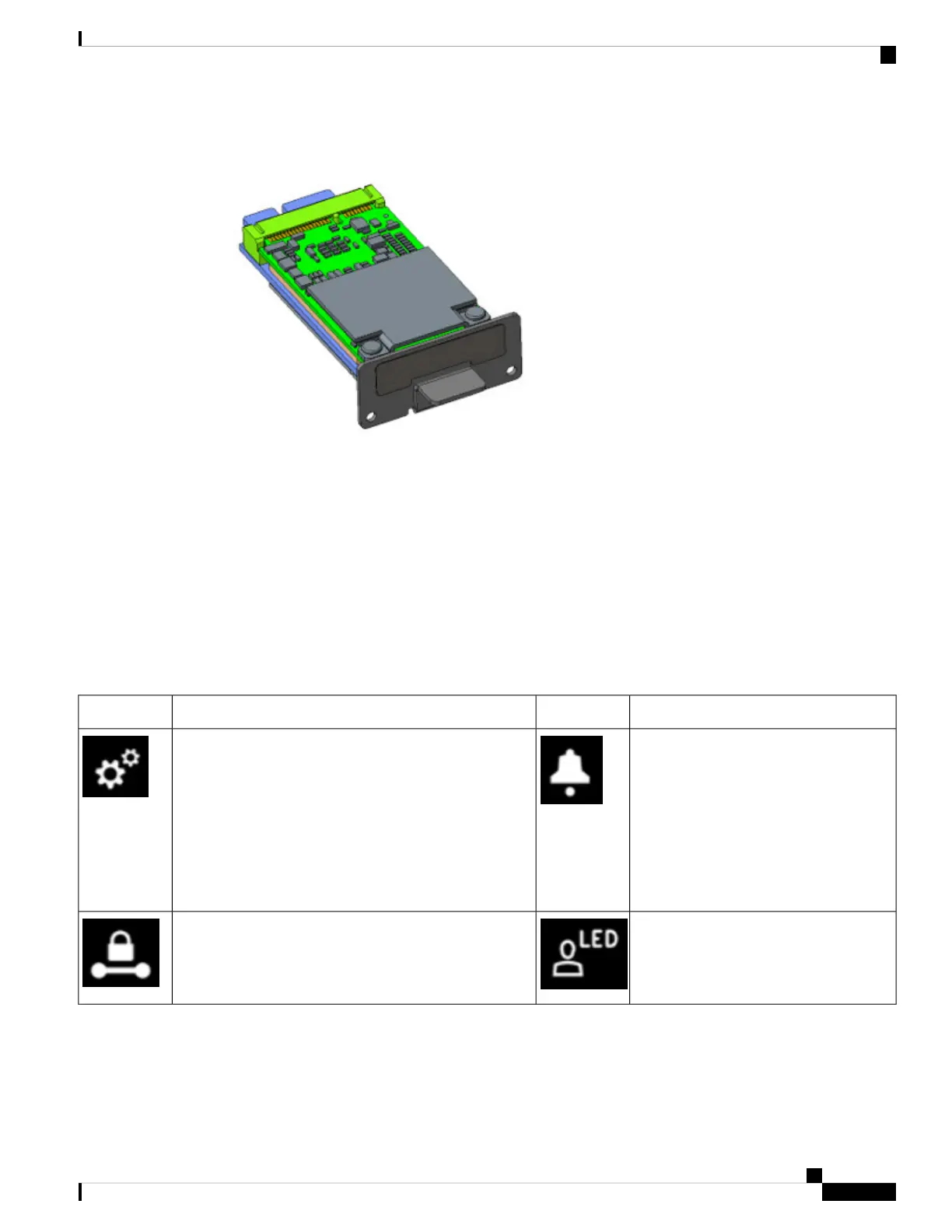
Figure 10: mSATA Pluggable Module
Highlights of the mSATA Pluggable Module are:
• Provides an additional 100GB of additional flash memory storage
• Main purpose is to provide space to store application data for IOx
• Field Replaceable unit, but is not hot-swappable.
Front Panel Icons and LEDs
The IR1100 Series uses icons to show the different features of the device. Table 6 shows Icons and their
associated LEDs with descriptions. Table 7 shows the Icons without associated LEDs and their descriptions.
Table 6: Icons with LEDs
Description/ActivityIconDescription/ActivityIcon
Alarm - Alarm Input Status
Off — Normal operation
Red - Alarm State on the Alarm Input
System - Power and System Status.
Off — No power
Green Steady on — Normal operation
Green Flashing — Boot up phase or in ROM Monitor
mode
Amber Steady on — Power is OK but possible internal
failure
Red, Green, and Blue User Configurable
LED
VPN
Off — No VPN tunnel
Steady Green — At least one VPN tunnel is up
IR1101 Industrial Integrated Services Router Hardware Installation Guide
19
Product Overview
Front Panel Icons and LEDs