Send document comments to nexus7k-docfeedback@cisco.com
7-15
Cisco Nexus 7000 Series Hardware Installation and Reference Guide
OL-23069-06
Chapter 7 Managing the Switch Hardware
Power Supply Configuration Modes
–
Input source redundancy mode—To activate this power mode, use the
power redundancy-mode insrc_redundant command. The reserve power is the greater of
power outputs for the two grids, and the available power becomes the lesser of power outputs
for the two grids.
For example, suppose your system has the following setup:
Grids 1 and 2 each input 220 V to the power supply units.
Power supply units 1 and 2 each output 6 kW.
Current usage requirement is 8.784 kW.
The following three scenarios explain what happens for different numbers of power supply units
that you install:
Scenario 1: If you do not add a power supply unit, the reserve power is 6 kW (3 kW for one
power supply unit and 3 kW for the other power supply unit), and the available power is 6 kW
(3 kW for one power supply unit plus 3 kW for the other power supply unit). The available
power does not meet the switch usage requirement, so you cannot power the entire switch.
Scenario 2: If you add a power supply that outputs 3 kW, the reserve power is 9 kW (3 kW for
three power supply units), and the available power is 6 kW (3 kW for each of two power supply
units). The available power does not meet the system usage requirement, so you cannot power
the entire switch.
Scenario 3: If you add a power supply unit that outputs 7.5 kW, the reserve power is 9.75 kW
(3 kW for two power supply units and 3.75 kW for the new power supply unit), and the available
power is 9.75 kW (3 kW for two power supply units and 3.75 kW for the new power supply
unit). The available power exceeds the switch usage requirement, so you can power up all of the
modules and fan trays in the switch.
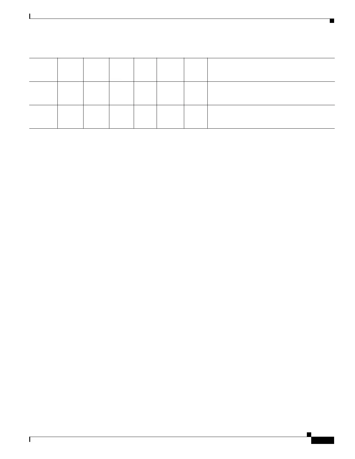
Table 7-5 shows the results for each scenario.
2 3.0 6.0 3.0 8.784 6.0 6.0 The available power does not meet the system
usage, so you cannot power the entire system with
this power supply configuration and mode.
3 3.0 6.0 7.5 8.784 9.0 7.5 The available power exceeds the system usage, so
you can power the entire system with this power
supply configuration and mode.
Table 7-4 Power Supply Redundancy Mode Scenarios (continued)
Scenario
Power
Supply 1
(kW)
Power
Supply 2
(kW)
Power
Supply 3
(kW)
System
Usage
(kW)
Available
Power
(kW)
Reserve
Power
(kW) Result

 Loading...


