Send document comments to nexus7k-docfeedback@cisco.com
1-4
Cisco Nexus 7000 Series Hardware Installation and Reference Guide
OL-23069-06
Chapter 1 Overview
Cisco Nexus 7000 Series
Figure 1-2 Standard Hardware Features on the Rear of a Cisco Nexus 7009 Chassis
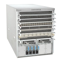
Note Figure 1-1 and Figure 1-11 show the Cisco Nexus 7009 chassis as it appears when it is fully configured
before including cables for connections to the Internet and the console. The systems that are not fully
configured with the maximum number of supervisor modules, I/O modules, fabric modules, or power
supply units have blank panels installed in place of the missing components to maintain the designed
airflow for system cooling.
You must install the Cisco Nexus 7009 chassis in a two- or four-post 19-inch EIA rack that meets the
following specifications:
• Mounting rails that conform to the English universal hole spacing as specified in
ANSI/EIA-310-D-1992.
• The minimum vertical rack space is 24.5 inches (62.2 cm) or 14 rack units (RU) for a single chassis
installation (15 RU if you use the bottom support rails, which are required for center-mount
installations and optional for front-mount installations).
Install the Cisco Nexus 7009 chassis at the lowest possible RU on the rack for stability. If there is another
device in the rack, install the heaviest chassis at the bottom.
1 Fan tray (1) 2 Power supply units (1 or 2)

 Loading...


