E-6
Cisco Wireless LAN Controller Configuration Guide
OL-9141-03
Appendix E Logical Connectivity Diagrams
Catalyst 3750G Integrated Wireless LAN Controller Switch
Catalyst 3750G Integrated Wireless LAN Controller Switch
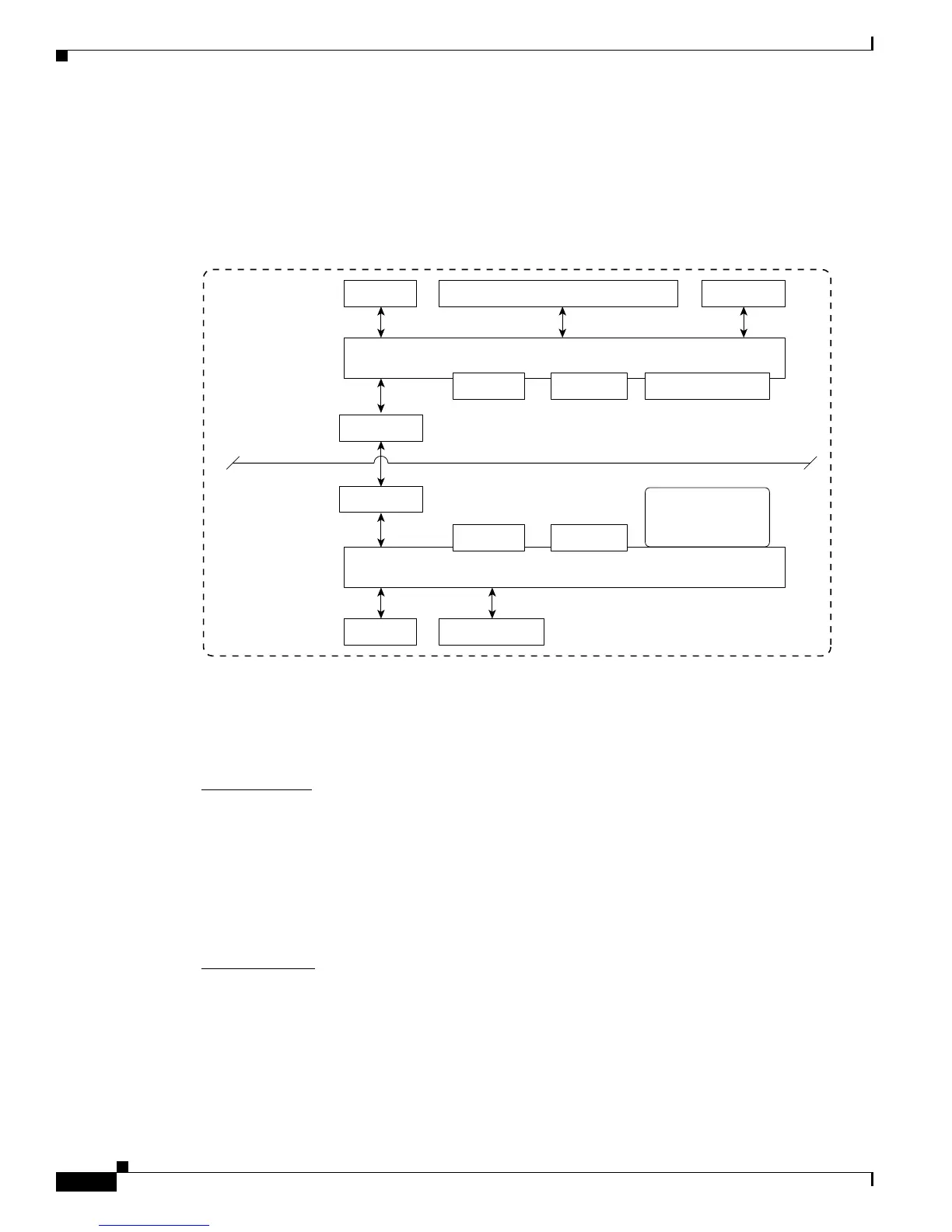
Figure E-3 Logical Connectivity Diagram for the Catalyst 3750G Integrated Wireless LAN
Controller Switch
These commands are used for communication between the Catalyst 3750G switch and the 4402
controller.
Login Command
This command is used to initiate a telnet session from the switch to the controller:
session switch_number processor 1
Because there can be several switches in a stack, the switch_number parameter is used to indicate to
which controller in the stack this session should be directed. Once a session is established, the user
interacts with the controller CLI. Entering exit terminates the session and returns the user to the switch
CLI.
Show Commands
These commands are used to view the status of the internal controller. They are initiated from the switch.
• show platform wireless-controller switch_number summary
Information similar to the following appears:
Switch Status State
1 up operational
2 up operational
3750G Switch
4402
Controller
Hidden
G1/0/27
G1/0/28
155911
24 Gig PoE Ports
Switch Motherboard
Controller Motherboard
Console
Console Gig E Service
RS-232 Serial
at 9600 baud
Ethernet
2 SFP Ports
G1/0/1 through G1/0/24
RS-232 Serial
at 9600 baud
G1/0/25
G1/0/26
2 SFP Ports
Hidden
Port 1
Port 2
2 SFP Ports
Memory Boot Flash Flash File System
Memory Boot Flash
Flash File System
on CF Card
Do not remove
 Loading...