3-3
Cisco Wireless LAN Controller Configuration Guide
OL-9141-03
Chapter 3 Configuring Ports and Interfaces
Overview of Ports and Interfaces
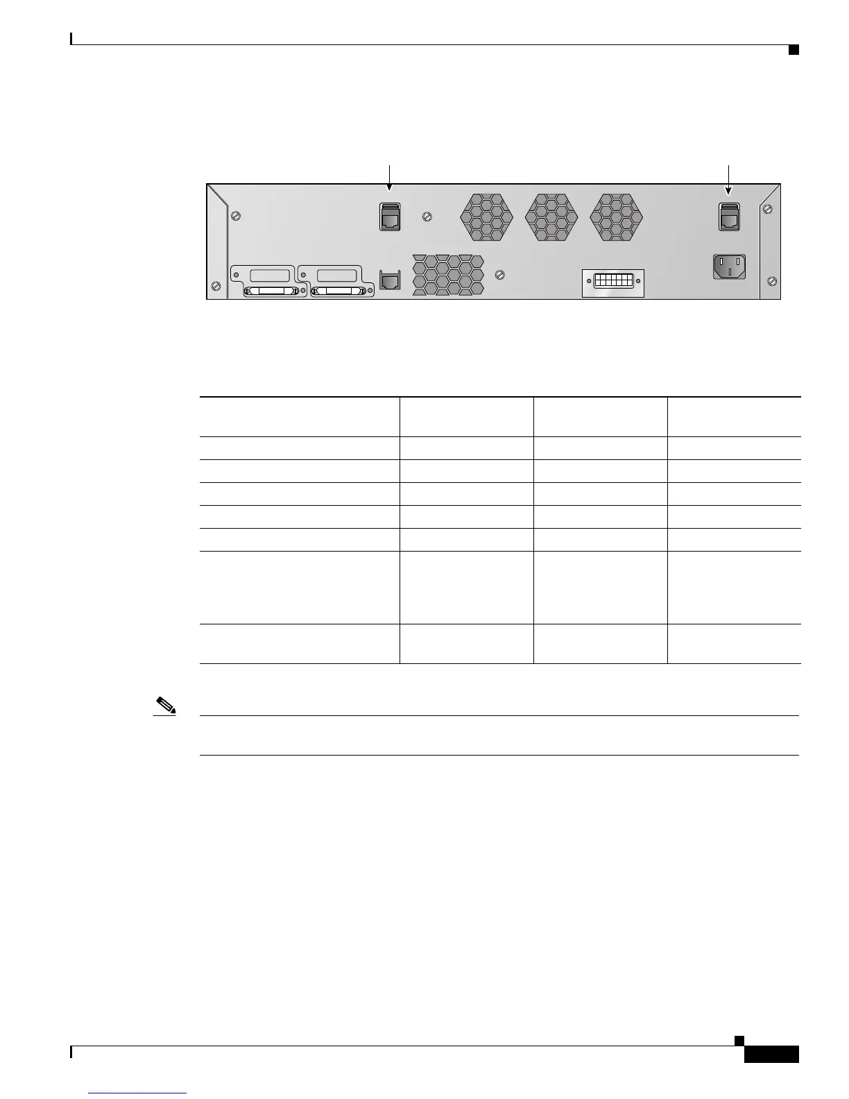
Figure 3-3 Ports on the Catalyst 3750G Integrated Wireless LAN Controller Switch
Table 3-1 provides a list of ports per controller.
Note Appendix E provides logical connectivity diagrams and related software commands for the integrated
controllers.
Distribution System Ports
A distribution system port connects the controller to a neighbor switch and serves as the data path
between these two devices.
• Cisco 2000 series controllers have four 10/100 copper Ethernet distribution system ports through
which the controller can support up to six access points.
• Cisco 2100 series controllers have six 10/100 copper Ethernet distribution system ports through
which the controller can support up to six access points. Ports 7 and 8 can function as PoE ports.
155755
Controller console
port
Service
port
STACK1 STACK2
SWITCH
CONSOLE
CONTROLLER
CONSOLE
SERVICE
Table 3-1 Controller Ports
Controller Service Ports
Distribution System
Ethernet Ports Serial Console Port
2000 series None 4 1
2100 series None 6 + 2 PoE ports 1
4402 1 2 1
4404 1 4 1
Cisco WiSM 2 (ports 9 and 10) 8 (ports 1-8) 2
Controller Network Module
within the Cisco 28/37/38xx
Series Integrated Services
Routers
None 1 1
Catalyst 3750G Integrated
Wireless LAN Controller Switch
1 2 (ports 27 and 28) 1