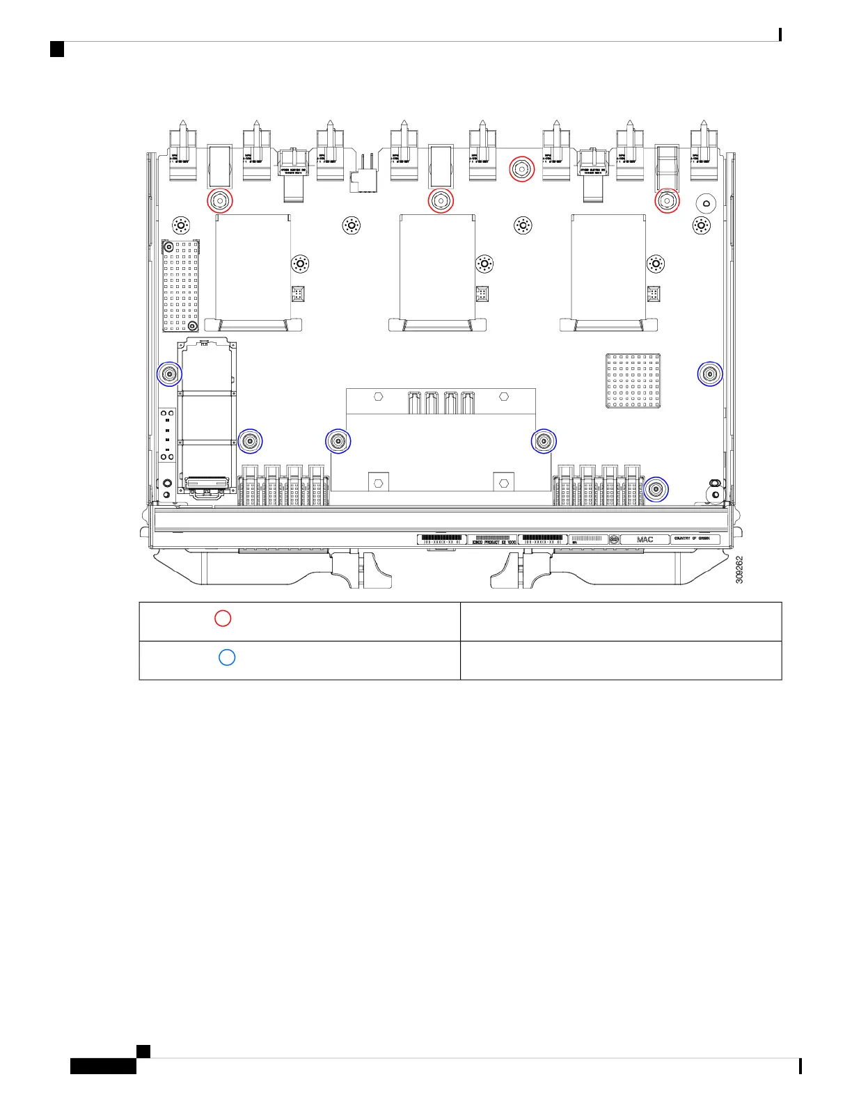
M3 hexagonal standoffs, 4
Red circles ( )
M3 screws, 6
Blue circles ( )
e) Grasp the PCBA and disconnect it from the sheet metal.
Step 5 Disconnect the remaining components from the PCBA.
a) Using the T10 screwdriver, remove the M3 screws for the top heatsink.
Cisco UCS X9508 Server Chassis Installation Guide
98
Installing and Removing Components
Recycling the UCS 9108 25G IFM PCBs
 Loading...