To remove the chassis printed circuit board assembly (PCBA), the following requirements must be met:
• The chassis must be disconnected from facility power.
• The chassis must have all compute nodes and IFMs removed. If they are not removed, remove them now.
Go to:
• Removing a Compute Node, on page 68
• Removing an Intelligent Fabric Module, on page 91
• The chassis must be removed from the equipment rack.
You will find it helpful to gather a T10, T15, and T20 screwdriver before beginning this procedure.
Step 1 At the rear of the chassis, remove the fan modules.
See Removing a Fan Module, on page 85.
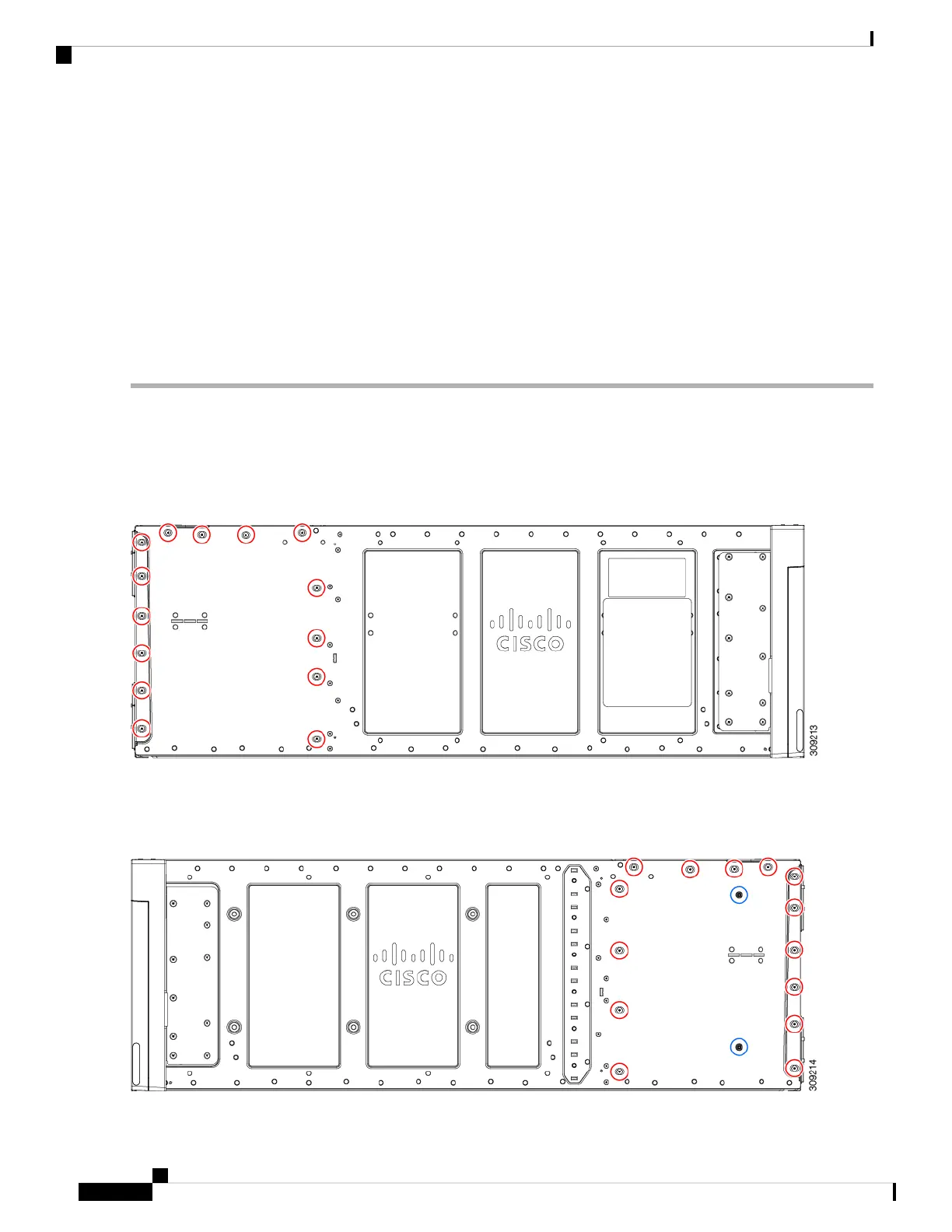
Step 2 On the left side of the chassis, use a T10 screwdriver to remove 14 M4 screws.
Figure 49: Cisco UCS X9508 Chassis, Left Side
Step 3 On the right side of the chassis, use a T10 screwdriver to remove 14 M4 screws plus the two captive M3 screws for the
PEMs.
Figure 50: Cisco UCS X9508 Chassis, Right Side
Cisco UCS X9508 Server Chassis Installation Guide
102
Installing and Removing Components
Recycling the Chassis PCB Assembly (PCBA)
 Loading...