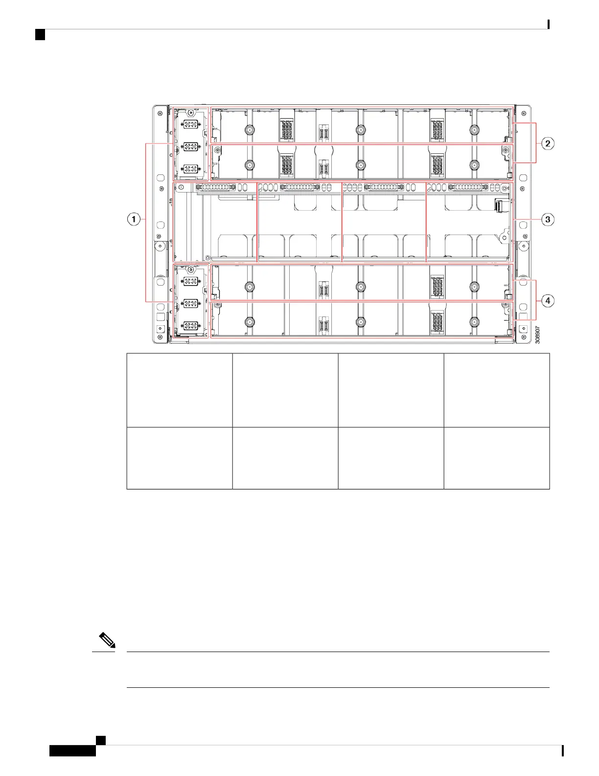
Figure 29: View of the UCS X9508 Server Chassis, Rear View
IFM slots (2)2Power Entry Modules (2)
Each PEM houses three
IEC 320 compatible C20
power inlets inlet facility
power.
1
Expansion Slots (2)4Fan Bays (4)
Fans are numbered 1
through 4 with fan 1 as
the leftmost.
3
The top of the chassis rear contains up to two Intelligent Fabric Modules (IFMs). Power connections and
minimal singaling are supported through the per-slot socket connections to the midplane. Three vertically
stacked Power Entry Module (PEM) connectors are also supported, which correspond with PSUs one through
three, with PSU one as the topmost connector.
The middle of the chassis rear houses up to four fan modules and power is supplied through one connector
per fan module. Fans are numbered from one to four with Fan 1 being the leftmost fan, and Fan 4 being the
right most.
The bottom of the chassis rear houses two active fan modules. Power connections and minimal signaling are
supported through the per-slot socket connections to the midplane. Three vertically stacked PEM connectors
are also supported, which correspond with PSUs four through six, with PSU four as the topmost connector.
Before you install, operate, or service the system, see the Regulatory Compliance and Safety Information for
Cisco UCS for important safety information.
Note
Cisco UCS X9508 Server Chassis Installation Guide
60
Installing and Removing Components
Components