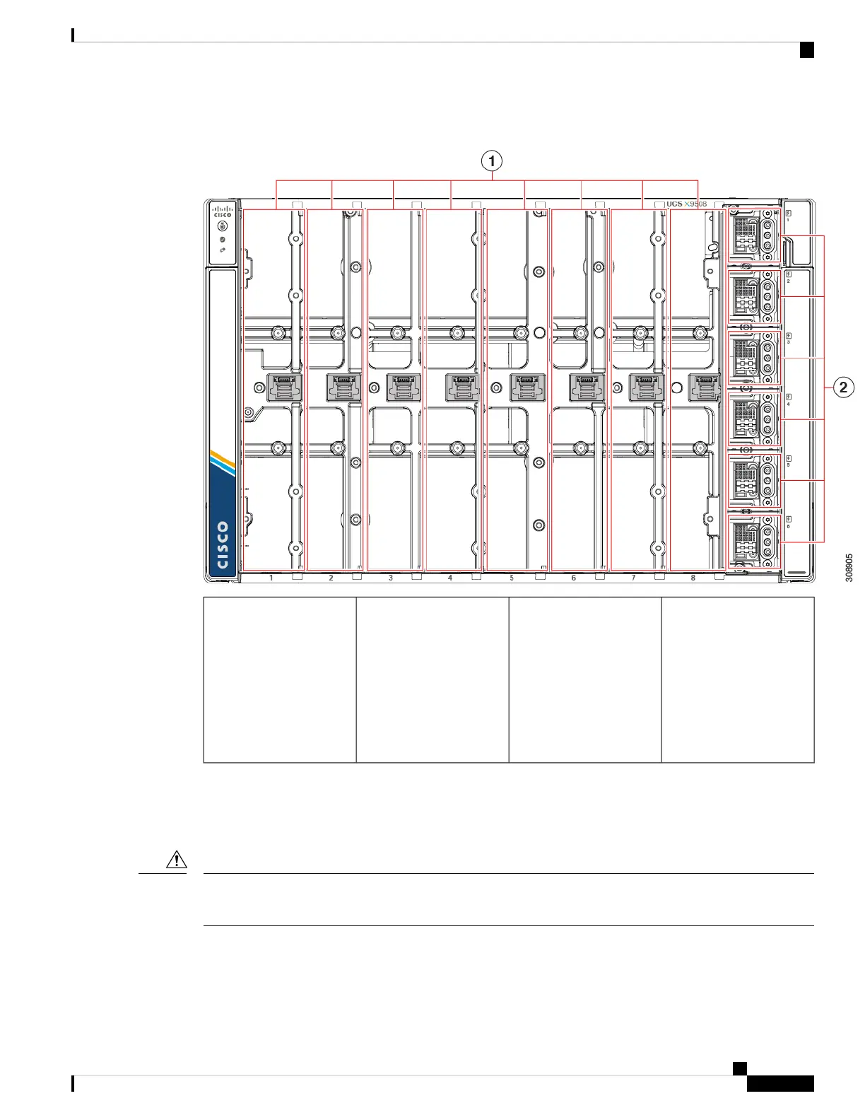
Figure 28: View of Empty Cisco UCS X9508 Chassis, Front
PSU bays (6).
Each PSU bay is
numbered vertically to the
right of the bay.
Each PSU bay is keyed so
that the PSU inserts only
one way.
2Compute Node slots (8).
Each slot is numbered
horizontally below each
slot.
Compute nodes can be
inserted vertically and
connect to the power
socket for each slot.
1
The front of the chassis accepts up to 8 Cisco UCS X210c M6 compute nodes with connections for power
and basic signaling through the per-slot socket connections to the midplane. The front of the server chassis
also hosts up to 6 PSUs providing power to the chassis power plane through internal connectors. PSUs are
numbered one through six with PSU bay one as the topmost slot and PSU bay 6 on the bottom.
Any compute node slot that is not occupied must have a compute node blank panel (UCSX-9508-FSBK)
installed.
Caution
Cisco UCS X9508 Server Chassis Installation Guide
59
Installing and Removing Components
Components