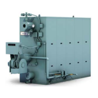
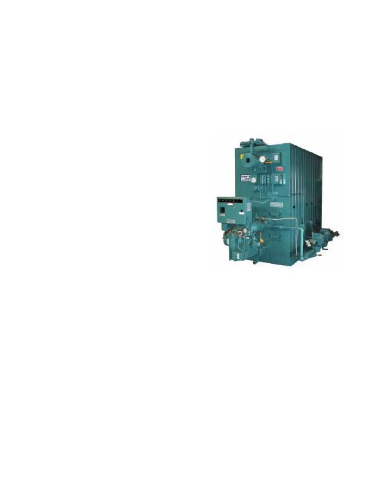
Model FLE Assembly General Description
750-192 1-5
Note:
• Building the vessel in a vertical position will require
support from the top.
• Drum placement is best accomplished when the base
is used as an initial building jig.
• A steam boiler will become structurally rigid with the
coupling of the front and rear Downcomers.
• Check the levelness of the base to the lower drum
and subsequently the Downcomers and upper drum
frequently.
Full sledge hammer swings, organized tube delivery
and efficient clamping, will build a rhythm allowing
for the installation of a side of 40 tubes in two to
four hours.
The base of the boiler must be leveled before the
pressure vessel is mounted and fixed. Level the ends
first, followed by the sides at both corners
After building, mounting, leveling and securing the
pressure vessel, a leak test must be performed. The
test requires that all open fittings on the drums be
plugged or valved for the test. Refer to the
Dimension Diagram for fittings required.
5. Casing Assembly
Installing the casing will require:
• Front-end and rear-end walls and collar plates
•Roof
• Inner Casing panels
• Burner door
•Fasteners
• Insulation (ceramic fiber blanket and wet pack)
•Gaskets
• High temperature silicon sealant
• Outer casing
• Drum Spreader (hot water units)
The tools required to install the casing include:
• Hand tools, 1/2” drive ratchet and sockets
• Wedges or dulled chisel
• Pry bars and tapered alignment pins
• Cartridge caulk applicator
• Slings and chains
• Lifting devices (come-along, ratchet hoist, etc.)
• Razor knife, putty knife
• Four, 5 foot bar clamps
Figure 1-5. Model FLE (Hot Water)