General Description Model FLE Assembly
1-4 750-192
3. Order of Assembly
The assembly of the pressure vessel and casing will
be easier if all of the component parts are sorted
and arranged to be easily accessible in the working
area. If there is not enough room in the work area
for all the parts, only those that will be needed for
the day’s work should be brought into the work
area.
Assembly of the boiler can be regarded as a four
step process. The four steps are:
1. Pressure vessel assembly and
water side leak test (Chapter 2)
2. Casing assembly and fireside leak
test (Chapter 3)
3. Burner assembly and gas train
installation (Chapter 4)
4. Trim installation (Chapter
4)
The boiler components are listed in Table 1-1.
Special assembly equipment likely to be required for
each part of the assembly process is listed below.
There are three different types of insulation used in
the construction of the Cleaver-Brooks Flextube
Model boilers:
• Ceramic fiber- white, flexible, dry insulation, supplied
in bulk roll or block
• Wet-pack- white, flexible, insulation saturated with
curing agent, supplied as rolls in sealed bags
• Fibrefax- white insulation, supplied in tubes
4. Pressure Vessel Assembly
Assembly of the pressure vessel will require the
following components (also refer to the packing list):
• Top and bottom drums
• Fanged bolts and gaskets
•Boiler tubes
• Base assembly
• Ceramic fiber pass seal insulation
• Tube sealant (LockTite 680)
• Anti-seize lubricant
• Tube retainers and fasteners
• Spray adhesive
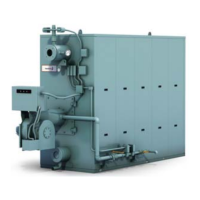
Figure 1-3. ProFire burner mounted on a Model FLE
boiler
The following tools will be required to assemble
the pressure vessel:
• Small and large level
• Vice-grip clamp or strap wrench
• Chain fall and support strapping
• Lifting support
• Tube driving tools and 16 or 20 lb sledge hammer
•5/8” die
• Dulled chisel
• Slings and chains
• Lifting and support devices (come-along, ratchet
hoist, etc.)
• Caulking gun
• Safety glasses, hearing protection and gloves
• Suitable lifting equipment will be required to handle
the placement of the drums and the mounting of the
completed vessel to the base
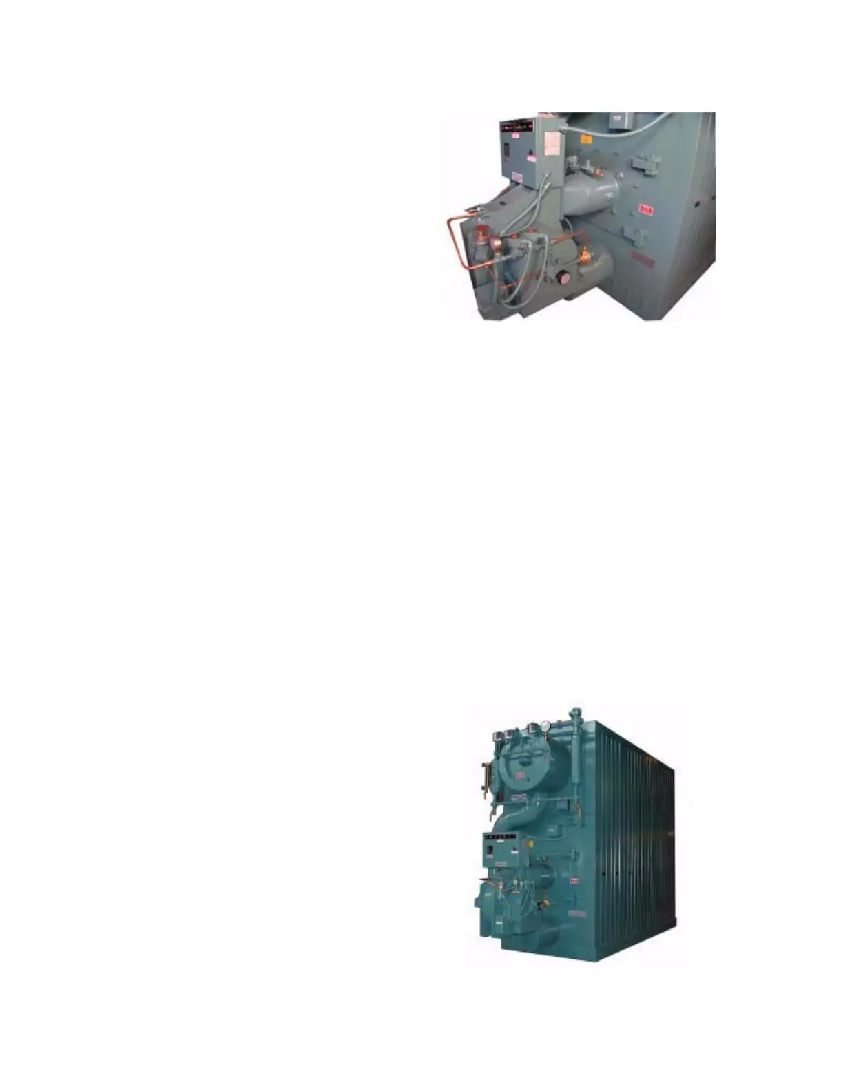
Figure 1-4. Model FLE (Steam)