Model FLE Assembly General Description
750-192 1-1
CHAPTER 1
General Description
1. The Boiler . . . . . . . . . . . . . . . . . . . . . . . . 1-1
2. Transportation and Handling . . . . . . . . . . . 1-2
3. Order of Assembly . . . . . . . . . . . . . . . . . . 1-4
4. Pressure Vessel Assembly . . . . . . . . . . . . . 1-4
5. Casing Assembly . . . . . . . . . . . . . . . . . . . 1-5
6. Burner and Fuel Piping Installation . . . . . . . 1-7
7. Trim Installation . . . . . . . . . . . . . . . . . . . . 1-7
1. The Boiler
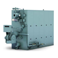
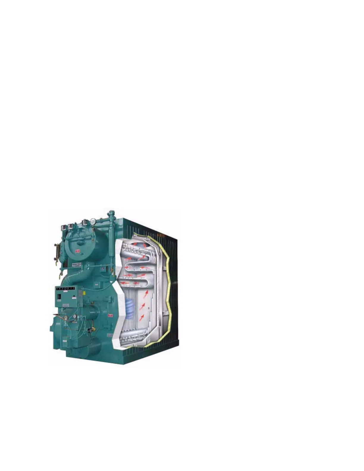
The Cleaver-Brooks Model FLE Boiler is a field-
erectable, five-pass, steel boiler. Its flexible,
replaceable, water-tubes are formed and arranged to
direct the flow of combustion gases through the
boiler as illustrated in Figure 1-1.
Figure 1-1. Five-Pass Construction of the Cleaver
Brooks Model FLE Boiler
The hot water unit has a single rear flanged external
rear downcomer while the steam unit has flanged
downcomers on both the front and rear. All units
have top and bottom drums. In the hot water unit,
the top and bottom drums are the same diameter,
but in the steam units, the top drum of a steam unit
is larger than the bottom. The pressure vessel is
designed and fabricated in accordance with the
ASME Boiler and Pressure Vessel code.
The heated area of the pressure vessel is contained
within an insulated casing that is composed of
removable, formed steel panels. The fuel/air mixture
from the burner combusts in the furnace area, then
exit the furnace (pass one) to flow through four
additional front-to-back passes formed by the
arrangement of the watertubes within the boiler
casing. In the fifth pass, the gases flow around the
top drum before exiting the boiler casing through the
stack vent.