Model FLE Assembly Pressure Vessel Assembly
750-192 2-15
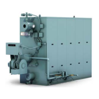
9. Pass Seals
Two lengths of ceramic fiber insulation seal the
sides of the upper gas passes. The pass seals are
installed between the contact areas of the left and
right side tubes as shown in Figure 2-26. The seals
are compressed and held in place as the left side
tubes are driven into place. Cut the seals from the
supplied bulk material. Use a spray glue to hold the
insulation in place while installing the left side
tubes.
WARNING
Gloves and an appropriate respirator should
be worn when handling or working with
insulating materials. Handling or working with
insulating materials may result in skin
irritation or may pose a health risk from
inhaling insulation fibers.
Proceed with tube installation in the same manner
as with the previously installed right-side tubes,
following the proper tube pattern sequence for the
right-side tubes as shown in Figures 2-19, 2-20 and
2-21.
CAUTION
Model FLE boilers are equipped with two
lifting lugs located on the upper drum. The
lugs should be used to lift or to pull the boiler.
If the vessel is a Hot Water unit, be sure the
front spreader is securely bolted in place prior
to lifting or moving the unit. Do not lift or move
the boiler by pushing, prying, or pulling on the
tubes, or downcomer pipe. Failure to follow
these instructions could result in equipment
damage.
Figure 2-26. Install pass seals before installing left
side tubes
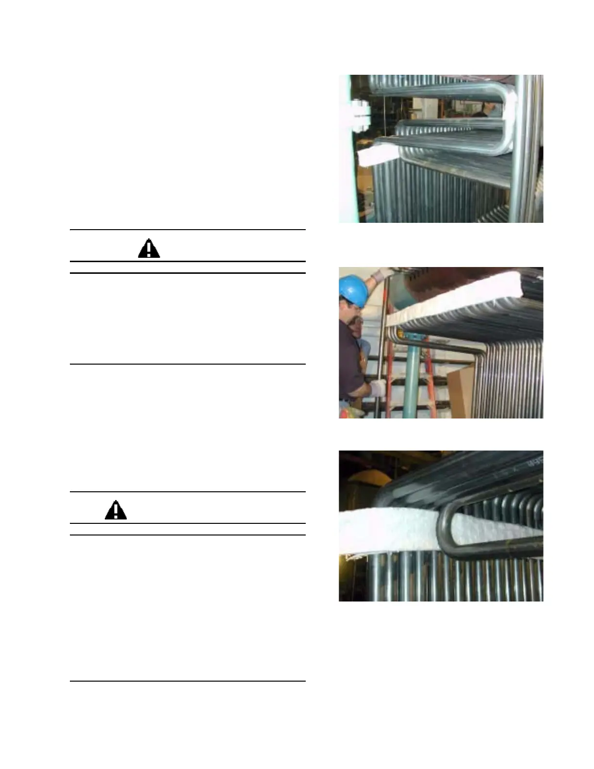
Figure 2-27. Upper pass seal installed
Figure 2-28. Lower pass seal installed