Casing Assembly Model FLE Assembly
3-20 750-192
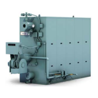
Figure 3-46. Trimming the excess gasket and wiping
the sealing surface
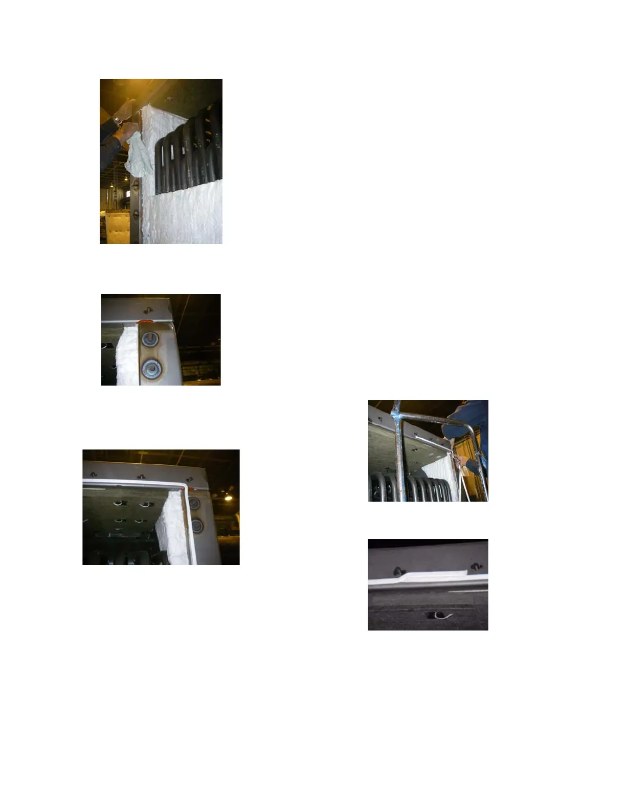
Figure 3-47. Silicone around the gasket at the seam
between the roof and the wall
Figure 3-48. Gasket positioned 1/8" from the inside
14. Prepare for Inner Casing Installa-
tion
• Using a box cutter, trim any gasket that shows
through the sides at the top of the front and back
sections. Clean the area. Wipe off the sealing surface
(the inside edge of the rear, and front walls, the roof
and the base) and remove any lumps (Figure 3-46).
• Apply silicone caulk (872-240) to the seam between
the roof and the end wall (Figure 3-47).
• Use extra pieced of insulation to fill the gaps near the
interior seams at the bottom of the front and rear
walls. After ensuring that the void is filled, clean the
area (bottom left corner of Figure 3-43).
• Apply the expanded PTFE gasket (32-2560) to the
boiler. The gasket should be positioned approxi-
mately 1/8" (Figure 3-48) from the inside edge of the
frame. Start at the front of the roof (Figure 3-49) and
run a continuous gasket around the entire side of the
boiler. Overlap the ends of the gasket by 3" or 4" by
running the gasket side by side, not crossing or on
top of each other (Figure 3-50). The gasket has an
adhesive strip attached; however, a spray adhesive
may be used to hold the gasket in place.
Figure 3-49. Gasket starts at the roof
Figure 3-50. Gasket Ends at the roof in a tight seal