Pressure Vessel Assembly Model FLE Assembly
2-6 750-192
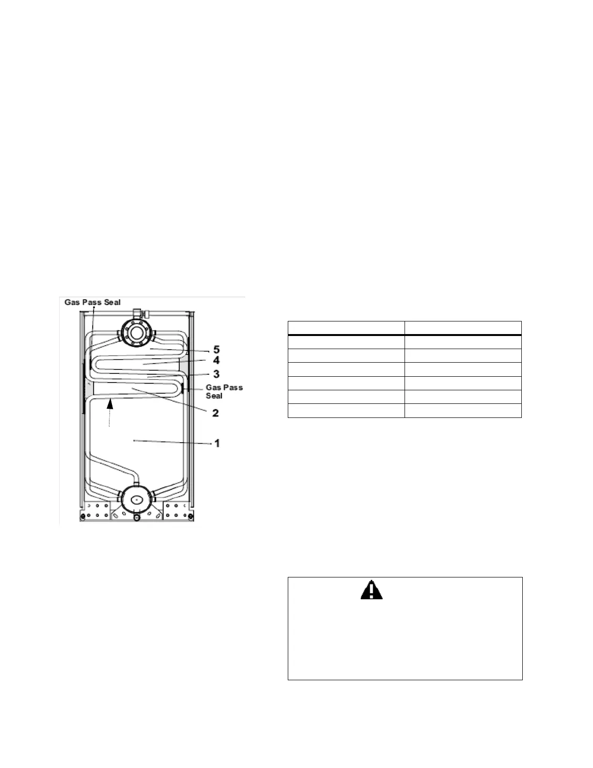
7. Tube Installation
Tubes are formed in eleven different patterns in
order to provide a five-pass gas flow path through
the boiler (Figure 2-10). Tubes can be identified by
visually comparing the tube profile to those shown
in Figures 2-17 and 2-18.
Figures 2-19, 2-20 and 2-21 show the proper
location for each tube pattern at the left and right
sides of the pressure vessel assembly. Tube
locations are the same for steam and hot water
units. The number at each pressure vessel tube
location in Figures 2-19, 2-20 and 2-21 refers to
the tube pattern numbers shown in Figures 2-17
and 2-18.
Figure 2-10. Cross section showing tubes forming
the five gas passes
Note: The horizontal tubes between the first
and second pass with a gap greater than 3/32”
must be packed with ceramic insulation.
One member of the assembly team should become
familiar with the boiler’s tube patterns and keep
track of the tubes as they are installed.
Inspect the tube ferrules for flat spots or scuffs due
to shipping. Repair or replace any tube that may
have been damaged during shipment
Tube installation should begin at the rear of the
pressure vessel, in order to take advantage of the
rigidity provided by the downcomer pipe. The
pressure vessel will become progressively more rigid
as additional tubes are installed.
Refer to pages 2-9 through 2-13 to determine the
top and bottom of the tubes. Install all of the tubes
on one side of the boiler.
Install the inner row left-side tube before the outer
row tube. Install the tubes in sequential order. Begin
installation of the left side tubes with a PATTERN 4
tube installed in the second to last position in the
upper drum (last tube hole in the bottom drum).
Install the vent tube PATTERN 3 next, followed by
the remaining left side tubes.
Table 2- 3: Inner and Outer Tube Patterns
Tube ferrule and drum socket surfaces must be free
of any dirt, corrosion, or petroleum-based lubricants
in order to ensure that the tube ferrule and sealant
work effectively
Tubes are driven into place with a tube driving tool,
(Figure 2-11) which is seated against a raised
shoulder on the tube ferrules. A 16-pound
sledgehammer is recommended for driving the
tubes.
INNER ROW TUBES OUTER ROW TUBES
Tube Pattern 4 Tube Pattern 1
Tube Pattern 5 Tube Pattern 2
Tube Pattern 9 Tube Pattern 3
Tube Pattern 10 Tube Pattern 6
Tube Pattern 11 Tube Pattern 7
Tube Pattern 8
WARNING
Heavy-duty work gloves and hearing and eye
protection must be worn by assemblers when
driving boiler tubes. Failure to heed this
warning may result in damage to the eyes,
hearing impairment, or serious personal
injury.