Model FLE Assembly Pressure Vessel Assembly
750-192 2-7
Use a modified vice-grip clamp to secure the driving
tool to the ferrule.
Before installing the tubes, apply a thin, uniform
coat of Lock-Tite sealant (Part Number 872-716) to
the first 1/2” of the ferrule and the drum socket
surfaces.
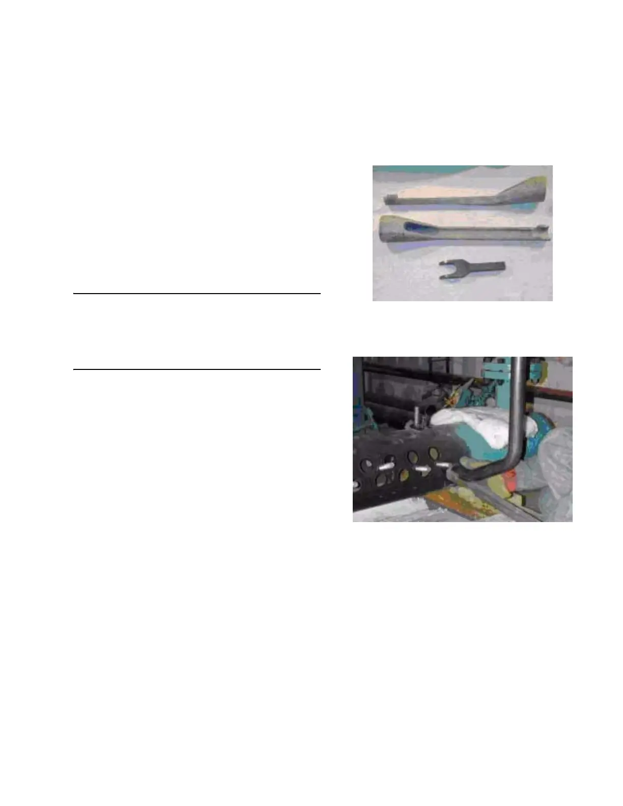
Both ends of the tube should be inserted into the
drum holes before the tubes are driven into place.
The driving tool must be securely held in place
against the tubes during the driving operation with
vice-grip type clamps (Figure 2-14).
Ferrules must be driven in to expose only 3/4 inch of
the tapered portion of the ferrule.
CAUTION - The tube driving tool must be securely
held against the tube during the driving operation.
Failure to do so is likely to result in damage to the
driving surfaces of the tube ferrule and the tube
driving tool.
The orientation of the first tube installed to the
drums will affect the location of all of the following
tubes. Check that the drums are level using a
bubble level. With the first tube loosely installed in
the drum sockets, place the bubble level against the
tube and adjust the orientation of the tube so that it
is perpendicular to the drums. When the orientation
of the tube is correct, drive them into the drums.
The tube ferrules must be correctly aligned with the
tube sockets when the tubes are being driven into
place in the drums. Although the taper on the
mating surfaces of the tube ferrule and tube hole
provide for alignment of the tube, misalignment
(cocking) may occur and is likely the cause of a tube
becoming difficult to drive before the required depth
of insertion is reached. In this case, remove the
tube, check the ferrule and socket surfaces for
damage and repair or replace it if necessary.
Reapply Lock-Tite® sealant to the ferrule and
socket surfaces, and reinsert the tube ends in the
drum sockets. After checking the tube alignment,
drive the tube ferrules into place with the difficult
ferrule first.
To achieve a tight fit between tubes, drive the tubes
to a uniform depth.
Install the remaining tubes on the right side, follow-
ing the proper tube pattern sequence as shown in
Figure 2-19, 2-20 and 2-21.
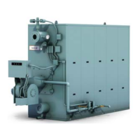
Figure 2-11. Tube Driving tools and Tube Removal
Tool
Figure 2-12. Driving lower end of first tube