Pressure Vessel Assembly Model FLE Assembly
2-14 750-192
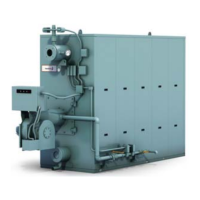
Figure 2-22. Ferrules must be driven in to expose
only 3/4 inch of the tapered portion of the ferrule
8. Ferrule Retainers
Tube ferrule retainers are provided to ensure
retention of the tubes and to prevent outward
movement of the tube ferrules as a result of
expansion and contraction during operation. The
retainers should be installed as the tubes are being
driven into the drums. When the first three tubes
have been inserted, secure the retainer before
inserting any more tubes.
Note: The ferrule retainers for the top and the
bottom are different.
Each retainer (except for the vent tube retainer and
end tubes) applies force upon several adjacent tube
ferrules. The retainers must be positioned so the
force is uniformly distributed on the driving surfaces
of the tube ferrules (see Figure 2-23 to 2-25)
WARNING - If overhead lifting points are used
to suspend or move the boiler components
during assembly, care must be taken to
ensure that the lifting points and the lifting
devices used are adequate to support the
weight of the components being carried.
Failure to heed this warning may result in
damage to the equipment or serious personal
injury or death.
CAUTION - Ferrule Retainers must be
installed as the tubes are being inserted.
Failure to do so can lead to the tubes popping
out.
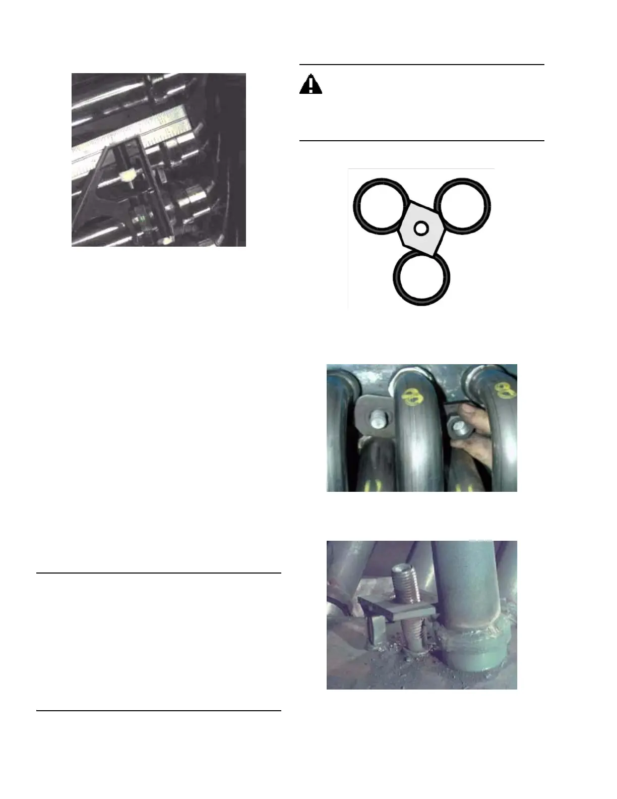
Figure 2-23. Rainier on the shoulder of a group of
three ferrules
Figure 2-24. Installing retainer on ferrule shoulders
Figure 2-25. Vent tube retainer (with welded tab)