750-192 4-1
CHAPTER 4
Burner Assembly, Gas Train,
and Boiler Controls Installation
1. Burner Mounting . . . . . . . . . . . . . . . . . . . 4-1
2. Burner Connections . . . . . . . . . . . . . . . . . 4-1
3. Gas Train Mounting . . . . . . . . . . . . . . . . . 4-1
4. Electrical Connections and Layout . . . . . . . 4-3
The burner used to fire the Model FLE series boiler
is mounted to a burner door which allows access to
the boiler combustion chamber for inspection and
maintenance. Fuel and electrical connections to the
burner must be made so as to allow the burner door
to be opened as intended.
1. Burner Mounting
Apply adhesive and a rope gasket to the burner
extension tube flange on the burner door. The rope
gasket should wrap around the burner extension
flange at lease 3 times. Apply the anti-seize
compound to the burner mounting studs.
Lift the burner and insert the burner extension tube
into the burner door opening. Install clamps,
washers, and nuts to the burner mounting studs.
With a bubble level atop the burner control cabinet,
level the burner. Tighten the mounting nuts evenly to
achieve a uniform compression of the burner flange
gasket.
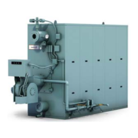
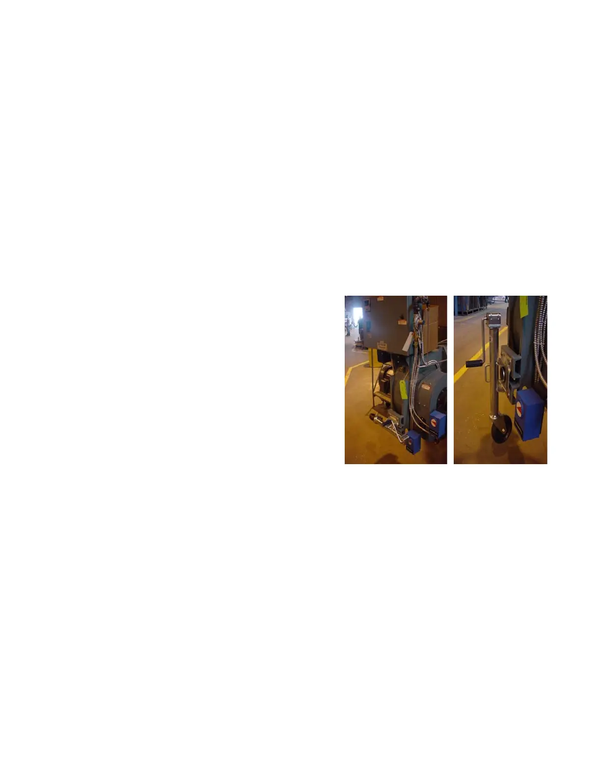
Bolt on the burner support. Smaller burners do not
require this support and it will not be provided for
them.
2. Burner Connections
Electrical and fuel connections to the burner must
be made in accordance with all applicable state and
local codes, as well as any insurers requirements
that may apply.
3. Gas Train Mounting
The gas train for a ProFire burner is mounted to the
base frame on the right side of the boiler.
The gas train components are shipped assembled
but mounting the gas train to the base and
plumbing to the burner is required in the field
assembly.
Check that all connections are tight following the
completion of the gas train plumbing (components
may have loosened or moved during shipping).
Pressurize the gas train with 1 psig of air pressure
and using a soapy water solution, either spray or
brush the solution on all connections. If bubbles are
evident, the suspected connection must be
disassembled and checked for damage. After
completing the inspection, seal, reassemble and re-
test the connection.
Figure 4-1. Burner Support