Pressure Vessel Assembly Model FLE Assembly
2-4 750-192
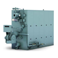
5. Upper Drum Placement
Using appropriately sized lifting devices, place the
upper drum in position above the downcomer and
lower drum. Apply sealant to the downcomer gasket
and position the gasket between the flanges. Using
the studs provided, secure the flanges and/or front
spreader bar. Apply “Never-Seez” to all flange studs.
This will establish the correct distance between the
drums at the front of a steam boiler and the rear of
both steam and hot water boilers. The correct drum-
to-drum spacing at the front of the boiler is
established by temporarily installing an adjustable
drum spreader. The drum spreader should be
installed at the end of the drums, as shown in
Figure 2-6. The part numbers for the drum
spreaders are shown in Table 2-2. See table 2-1 for
drum dimensions.
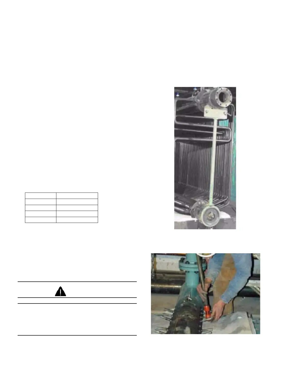
6. Check All Drum Holes and Studs
Drum Holes
Check all drum holes for any burrs, weld splatter or
distortion as any imperfections must be cleaned or
repaired. To clean burrs or welding spatter, use 150
grit emery cloth (Figure 2-7).
CAUTION
Drum holes may be sharp from the machining
process. Burrs and sharp machined edges can
cause severe cuts. Care must be taken when
inspecting drum holes.
Studs
If there are any threads causing the tube retainer
studs to bind, chase them with a 5/8” die (Figure 2-
8). Checking all the retainer stud threads will make
the assembly process go smoother. All retainer
studs must be coated with “Never-Seez”.
Figure 2-6. Drum spreader in position on completed
vessel
Figure 2-7. Use a 5/8" die to chase all the retainer
stud threads
Table 2-2 Drum Spreader Part Numbers for Hot Wa-
ter Units by Size
Size Part No.
150-250 98-317
300-350 98-323
400-600 98-318
700-1200 98-324