Model FLE Assembly Casing Assembly
750-192 3-1
CHAPTER 3
FLE Casing Assembly
Procedures
1. Install Wetpack around Vent Tube . . . . . . . 3-8
2. Install Backing Plates . . . . . . . . . . . . . . . . 3-8
3. Install Rear Wall Sections . . . . . . . . . . . . . 3-9
4. Drill Rear Sight Port . . . . . . . . . . . . . . . 3-12
5. Wetpack Installation Around Lower Drum . 3-14
6. Finish Installing Backing Plates . . . . . . . . 3-14
7. Install Front Wall Section . . . . . . . . . . . . 3-14
8. Install Roof Panel . . . . . . . . . . . . . . . . . . 3-14
9. Install Burner Door . . . . . . . . . . . . . . . . 3-16
10. Install Lift Lug Cover . . . . . . . . . . . . . . . 3-17
11. Install Drum Packing and Seal Plates . . . 3-18
12. Install Insulation Under Tubes . . . . . . . . 3-19
13. Install Pass Insulation . . . . . . . . . . . . . . 3-19
14. Prepare for Inner Casing Installation . . . . 3-20
15. Prepare Inner Panels for Installation . . . 3-21
14. Install Inner Casing . . . . . . . . . . . . . . . . 3-22
17. Install Outer Casing . . . . . . . . . . . . . . . 3-23
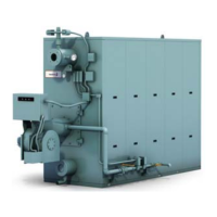
The casing of the Model FLE Boiler encloses and
forms a shell around the pressure vessel. Casing
panels are bolted together and can be removed for
inspection and servicing of the internal boiler
components. Casing panels must be installed and
fastened together in a specific order to ensure a
strong seal.
Casing panels are joined by bolts or studs and are
sealed by an expanded PTFE gasket material.
In addition to applying the gasket, a small amount
of Teflon paste and high temperature sealant,
supplied with the Model FLE assembly kit, is to be
applied to the indicated areas before the panels are
installed.
CAUTION
Model FLE casing panels are shipped with
insulation attached. Care must be taken when
handling casing panels In order to prevent
damage to the insulating materials.
CAUTION
Careful attention must be given to the
placement and integrity of casing joint gaskets
and seals during assembly to ensure a tight
seal. All casing joints must be completely
sealed against leakage of combustion gases.
Failure to ensure a tight seal at the joints may
result in leakage of combustion gases and will
cause damage to adjacent areas of the casing
panels during operation of the boiler.