Model FLE Assembly Casing Assembly
750-192 3-13
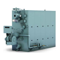
Figure 3-22. Direct guide pipe to end of tape
measure (flame location when assembled and
operating)
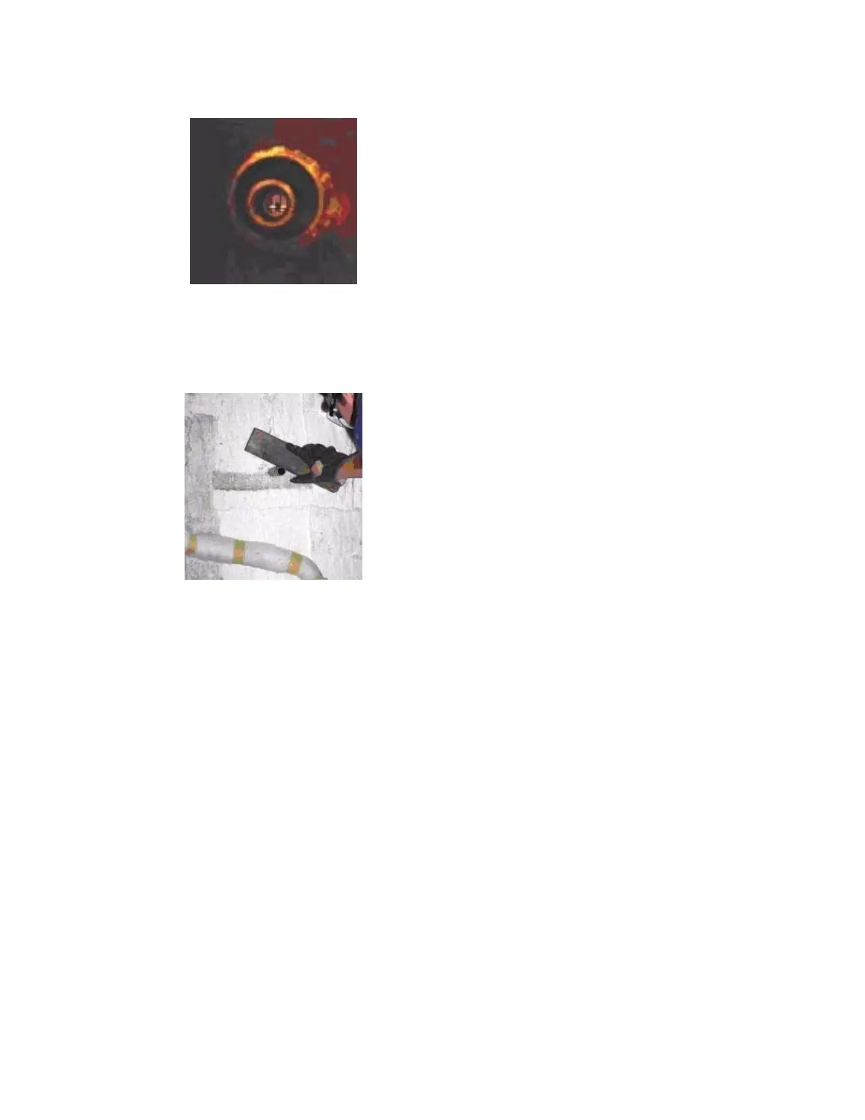
Figure 3-23. Pack insulation around sight port and
apply rigidizer to inside of sight port opening.
4. Insert the pipe from outside the boiler and direct it to
the top of the tape measure (Figure 3-22).
5. Clean up any loose insulation from outside and inside
the boiler.
6. Inspect the rear wall from inside the boiler. Push
together any open seams in the Pyrobloc insulation
and tap down the area. Pack the insulation inside the
boiler around the guide pipe ensuring that the open-
ing in the guide pipe is still pointing toward the top of
the tape measure. Pack the insulation so that there
are no gaps and if necessary, fill any cavities using
loose insulation removed from the drilling process.
After the insulation has been packed around the
guide pipe, remove the guide pipe (Figure 3-23).
NOTE:
The hole MUST be positioned to
view the tape measure. Repeat steps 4
and 6 until it is visible.
7. Coat the end of the ceramic fibre tube in fibrefax.
Insert the tube into the sight port so that it is touch-
ing the insulation.
8. To complete the rear sight port installation, install the
sight glass cap that comes with the casing assembly
kit.