Advanced M52 Microprocessor User's Guide
ADVANCED M52UMCT2019 COLOR 45
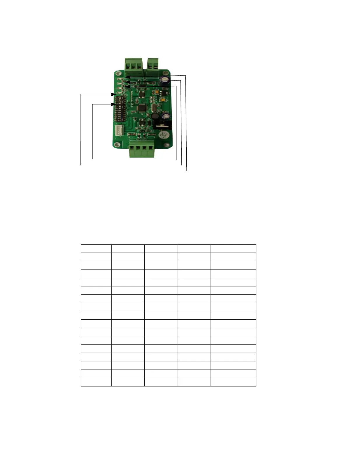
5. Sensor Hub
LED Power Indicator
ddress Jumpers SW2
ddress Jumpers SW1
LED Communication Mainboard
LED Communication Sensor
Fig 6 Sensor Hub
SW1 is the Switch for Main Board Communication.
SW2 is the Switch for Temperature and Humidity sensor.
P1 is the Power of the board,
P3 Connect multiple Temperature and Humidity Sensor.
P4 can connect to Main Board P502.
SW1 Table:
RS485
4
3
2
1
1 0 0 0 0
2
0
0
0
1
3
0
0
1
0
4
0
0
1
1
5
0
1
0
0
6
0
1
0
1
7
0
1
1
0
8
0
1
1
1
9
1
0
0
0
10 1 0 0 1
11 1 0 1 0
12 1 0 1 1
13 1 1 0 0
14 1 1 0 1
15 1 1 1 0
16 1 1 1 1
Now we only use RS485 Address 11&12
RS485 Address 11 is the return Air Sensor.
RS485 Address 12 is the supply Air Sensor.