MBF-40 SMR700/SMR800 PS REPEATER
PRODUCT DESCRIPTION AND USER’S MANUAL
www.cobham.com/wireless Date: 28-Jan-16 Cobham Wireless – Coverage
Page | 4
Rev. 2.1 Doc. No. 00046UM
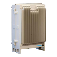
1.5.1 External Interfaces
NOTE: The external connections at the bottom of the repeater can be protected with a cover which is screwed
in place.
Figure 1-3: External Interfaces
Port Description
Server Service antenna connection - DIN 7/16” connector, female
Optic SC/APC Fiber optic inlet through which the optic Fiber is routed for internal
connections (section
2.3.5).
Power
Plinth connection for routing power for internal connection (section
2.3.7.1)
Alarms Plinth connector for routing external alarms and relay wiring cable for internal
connections (section
2.3.8).
GND
Grounding lug (section
2.3.3)
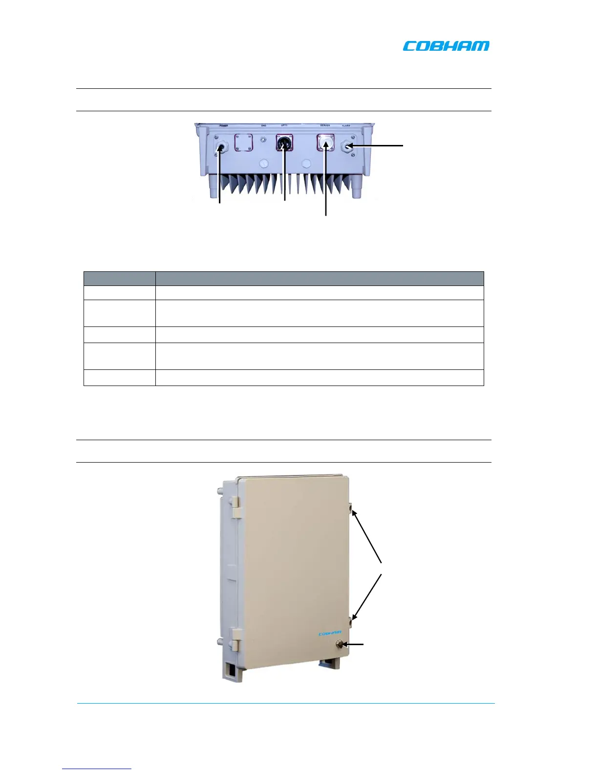
1.5.2 Securing the Unit
The repeaters are secured with two hex screws (M8) and can also be locked with a key.
NOTE: The two screws must be fully tightened. Failure to do so may affect the IP65 compliancy and therefore
any warranty.
Figure 1-4: Securing Dual Band