MBF-40 SMR700/SMR800 PS REPEATER
PRODUCT DESCRIPTION AND USER’S MANUAL
Cobham Wireless – Coverage Date: 28-Jan-16 www.cobham.com/wireless
Doc. No. 00046UM Rev. 2.1
Page | 5
1.5.3 Internal Interfaces
This section shows the internal interfaces relevant to the following operations:
• Connect power
• Connect optic Fibers
• Connect alarms (if relevant)
• Power-on (Power-ON switch)
• Optional – USB/Ethernet port for local setup
NOTE: The internal view of your repeater may be different, but the general location of the relevant items is the
same.
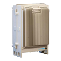
Figure 1-5: MBF Repeater with Door Open
Alarms and relay connections.
(Section
3.6)
USB local setup connections. Refer to
Section
7.4 for LED descriptions
Ethernet Local Setup port