MBF-40 SMR700/SMR800 PS REPEATER
PRODUCT DESCRIPTION AND USER’S MANUAL
Cobham Wireless – Coverage Date: 28-Jan-16 www.cobham.com/wireless
Doc. No. 00046UM Rev. 2.1
Page | 61
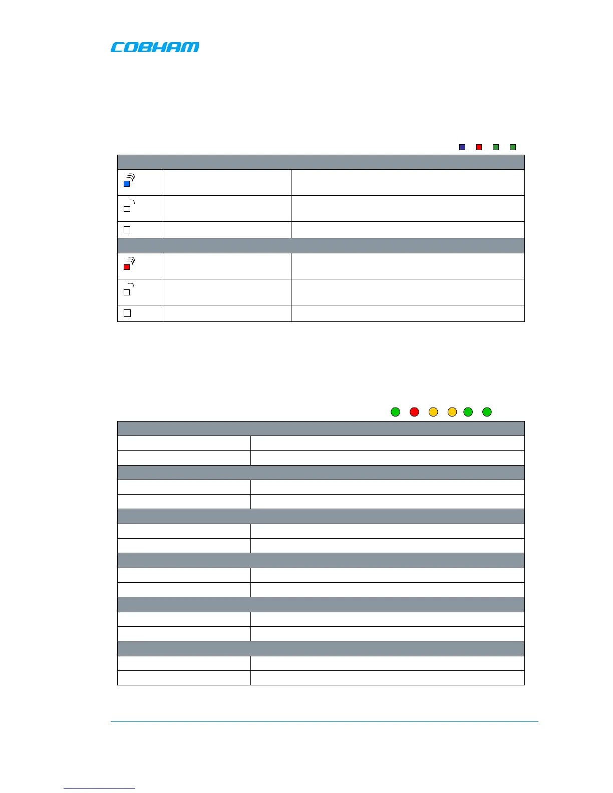
5.3.1 Control Module LEDs
The Control Module has four LEDs which give information regarding the
status of the MBF-40.
The two LEDs “Modem Power” and “Modem Status” do not fill any function
and can be disregarded.
Blue LED - Login
Quick flash Control Module switched on,
locally and/or remotely
Off (except for a quick flash
every 10th second)
Control Module switched on, no one logged in
Off (permanent) Control Module switched OFF
Red LED - Status
Quick flash Control Module switched on, one or more
errors/alarms detected
Off (except for a quick flash
every 10th second)
Control Module switched on, status OK
Off (permanent) Control Module switched off
5.3.2 F/O Converter LEDs
There are 6 LEDs on the module to indicate the status.
LED 1, Power, Green
On Unit is powered on
Off Unit has no power
LED 2, Error, Red
On Error detected
Off No error
LED 3, UL Data, Yellow
On Communication is ongoing in the uplink direction
Off No communication
LED 4, DL Data, Yellow
On Communication is ongoing in the downlink direction
Off No communication
LED 5, Opto Rx, Green
On Received RF signal on Fiber channel is above threshold
Off Input level below threshold
LED 6, Opto Tx, Green
On Transmitted RF signal on Fiber channel is above threshold
Off Output level below threshold