MBF-40 SMR700/SMR800 PS REPEATER
PRODUCT DESCRIPTION AND USER’S MANUAL
www.cobham.com/wireless Date: 28-Jan-16 Cobham Wireless – Coverage
Page | 38
Rev. 2.1 Doc. No. 00046UM
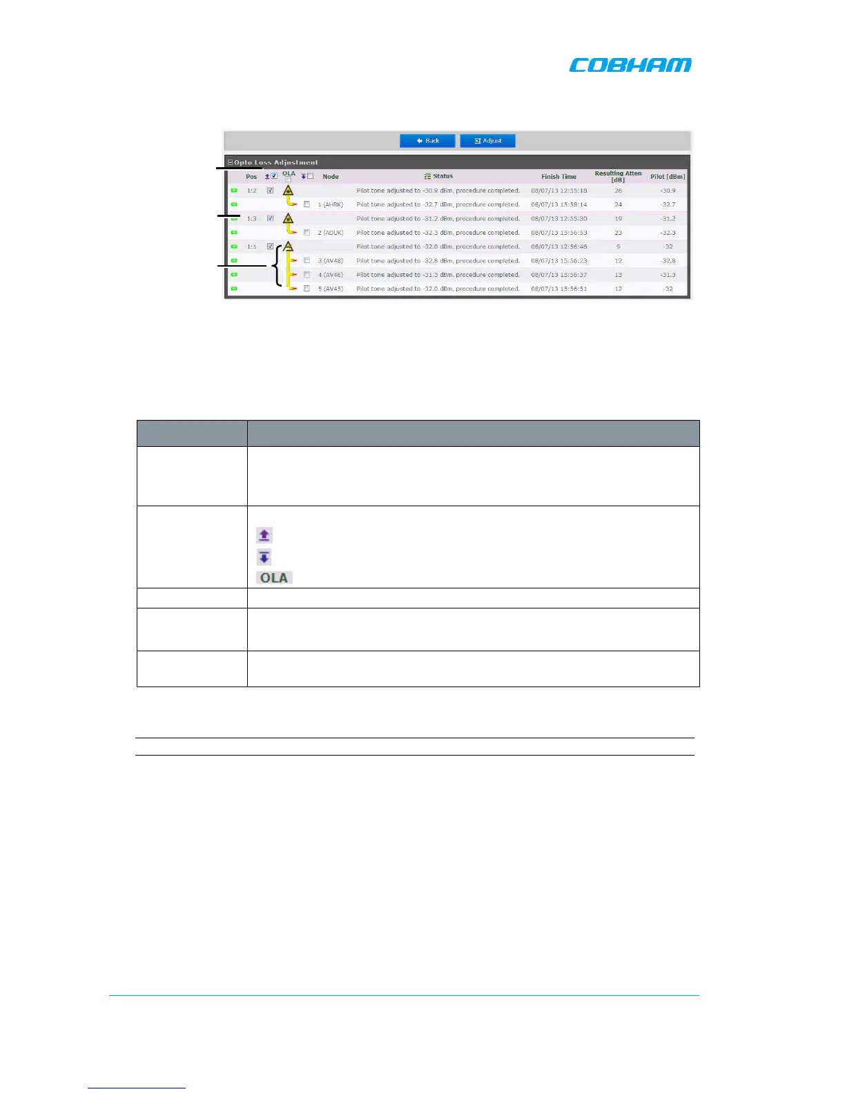
The OLA screen appears.
Figure 3-7. Configure and Initiate Optical Loss Adjustment
The screen lists the OLA options (and status) for each link. (The links are listed according to the
OMU II slot to which the remote is connected.).
A brief description of the OMU II OLA screen is given below.
Column Description
Pos Each Rack corresponds to an OMU unit whereas each Slot corresponds to
an Opto-Module. Slots are numbered according to their position in the OMU
Chassis (numbered left to right).
Select All Batch selection options:
- mark all remotes for UL opto-adjustment.
- mark all remotes for DL opto-adjustment.
- mark all remotes for DL and UL adjustment.
Node Node list number and identification (e.g. AHFK)
Status Displays an Error if process failed. If successful the pilot tone used and the
adjustment level will be displayed.
Resulting
Attenuation
Compensation level used for the opto-module (in dB).
3. Mark the check-boxes corresponding to the MBF UL/DL node to be adjusted.
NOTE: The process may take several minutes depending on the size of the system and remote distance.
Rack#:Opto-
Module