98-175666-D Appendix C: Miscellaneous C-5
Dual modem operation
The GMU uses the GX satellite profile of the SAILOR XTR GX-R2 system. The secondary
modem e.g. Comtech SLM-5650B Modem uses the generic satellite profile of the
SAILOR XTR GX-R2 system. The generic satellite profile must be configured to activate
a GPIO pin that activates the RF switch in order to switch in the Tx signal of the
secondary modem as well as switch out the Tx signal of the GX modem.
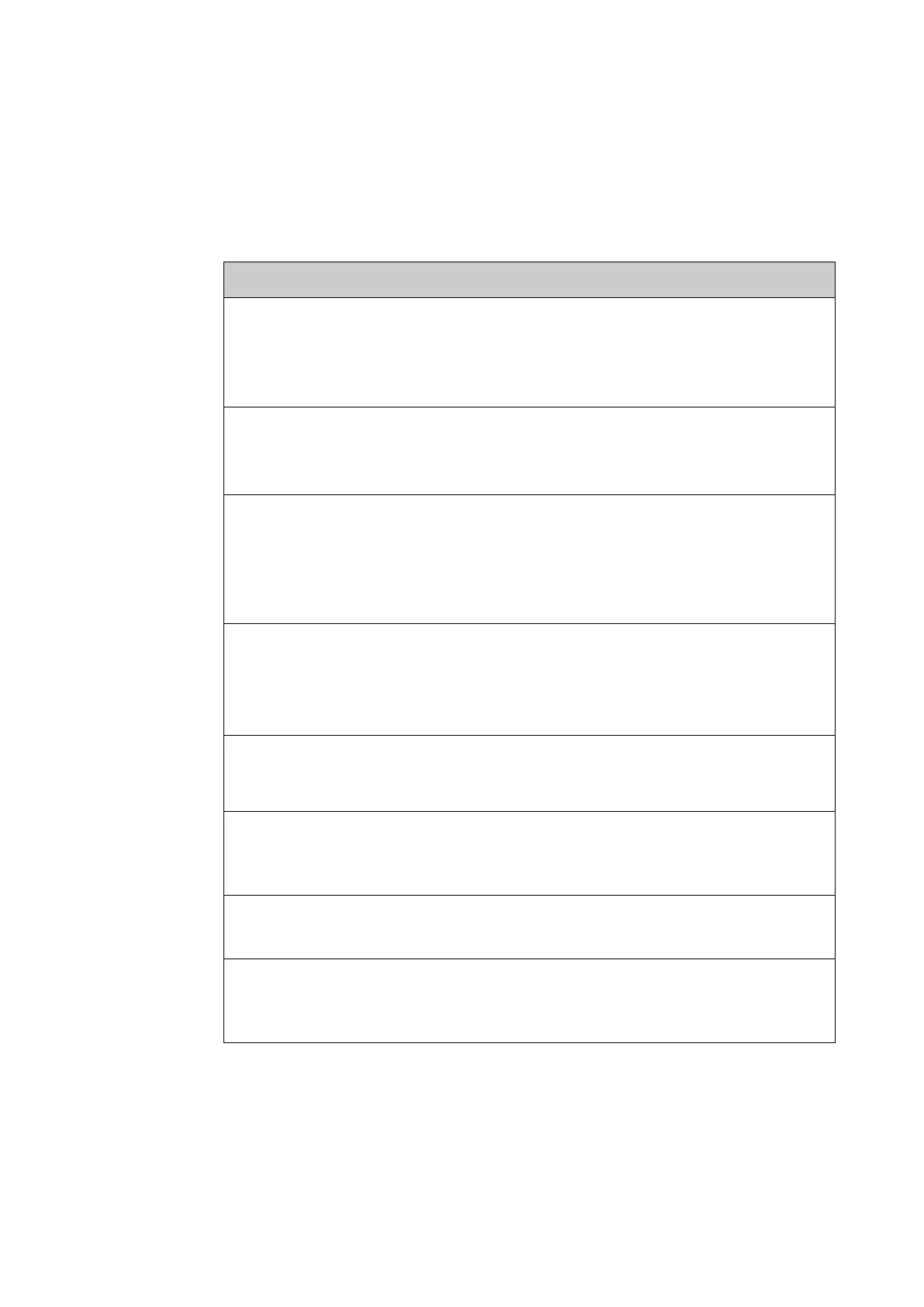
The below table lists and describes the different cables and accessories.
Cables and accessories Description
LAN cables Straight through all 8 wires.
• Used for communication between GMU and BDU.
• Used to connect power from the BDU GPIO port to
the RJ-45 to screw terminal adapter.
37-137756-A 0.5-meter 75Ω coax cable.
• Connects Tx from BDU to RF switch.
• Connects Rx from BDU to RF splitter output.
37-138211-A 1m 75Ω coax cable.
• Connects RF switch to Tx connector of the two
modems.
• Connects RF splitter to Rx connector of the two
modems.
37-176036-B RJ-45 to DB9 serial cable.
• Connects the BDU RS-422 to GMU RS-422.
Used for GMU to communicate with the GX-R2
Transceiver (BUC communication).
37-181724-A RJ-45 to DB9 and DB15 splitter cable to GMU Keyline
and Comtech 5650B modem AGC used for RX Lock
detection.
37-181725-A RF switch.
Controlled by the BDU to automatically switch Tx line
depending on which VSAT profile is activated.
46-137096-A RF splitter.
Used to split the BDU Rx signal to both modems.
31-208142-000 RJ-45 to screw terminal adapter.
Used to split power leads from the RJ-45 to the power
input of the RF switch.
Table C-2: Cables and accessories

 Loading...


