Site considerations
98-175666-D Chapter 2: Installation 2-4
Modifying the radome or using another radome
The SAILOR XTR GX-R2 antenna comes with a type-approved radome fitted from the
factory. This radome is specifically designed for a minimal loss of RF performance for
this specific antenna. Insertion loss reduces the available signal and decreases the
effective radiated power and G/T (the ability to receive a weak signal). Modifying the
radome or using another radome may increase the antenna side lobes, resulting in
interference with other communication systems and thereby void satellite operator
approvals. Other electrical effects on antenna performance of another radome, or of
modifying the radome, include a change in the antenna beam width and shifting of the
antenna bore sight.
Cobham Satcom recommends NOT to modify the radome or change it to another type.
Exchanging or modifying the radome will not void the general warranty for material
and workmanship etc. but the performance cannot be guaranteed, and the satellite
operator approvals will not be valid.
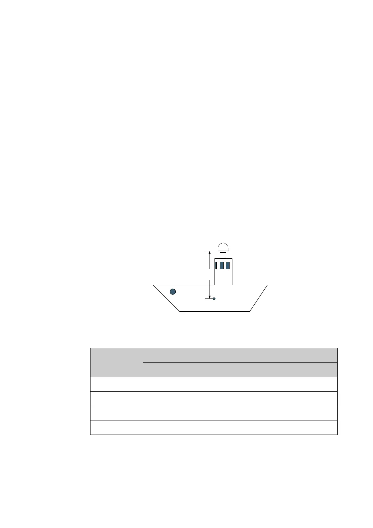
Ship motion and offset from the ship’s motion centre
When installing the ADU you must consider the mounting height carefully. The higher
up the ADU is mounted, the higher is the linear g force applied to the ADU. The g force
also depends on the roll period of the ship, see Table 2-2. If the g force applied is too
high, performance and ADU signal stabilization may be reduced and eventually the
ADU may be damaged.
Even though it is recommended to mount the ADU high, keep the distance between
the ADU and the ship’s motion center as short as possible.
Figure 2-1: Maximum distance from the ship’s motion centre (h max)
Minimum
roll period
Maximum ADU mounting height (h max)
Full performance Potential risk of damage
4 s 12 m 16 m
6 s 27 m 35 m
8 s 48 m 62 m
10 s 75 m 98 m
Table 2-2: Maximum distance from the ship’s motion center versus ship’s roll period

 Loading...


