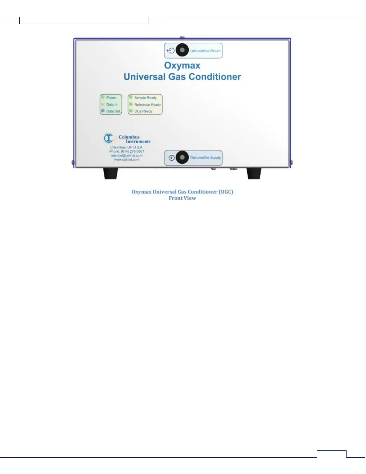
1. Power – A green light which indicates connection to a source of DC power.
2. Data In - A yellow light which indicates the host computer is transmitting data.
3. Data Out – A blue light which indicates the UGC is transmitting data.
4. Sample Ready - A green light which indicates the status of the gas sampling circuit.
OFF: The sampling pump or circuit is switched off.
FLASH: The humidity, flow, and pressure are moving toward their respective operating
setpoints.
ON: The humidity, flow and pressure are steady at their setpoints.
5. Reference Ready – A green light which indicates the status of the reference circuit:
OFF: the reference pump or circuit is switched off.
FLASH: The humidity, flow, and pressure are moving toward their respective operating
setpoints.
ON: The humidity, flow and pressure are steady at their setpoints.
6. CO2 Ready – A green light which indicates the status of the CO2 sensor
OFF: a) the sampling pump or circuit is switched off. b) the sampling circuit is switched
on and the CO2 sensor is warming up.
FLASH: A fault has been detected within the CO2 sensor.
ON: the CO2 sensor has reached operating temperature and reports valid
measurements.
7. Dehumidifier Return – The output port of gas to be dried for connection to the Drierite column(s).
8. Dehumidifier Supply – The input port of dry gas for connection from the particle filtered Drierite
column(s).