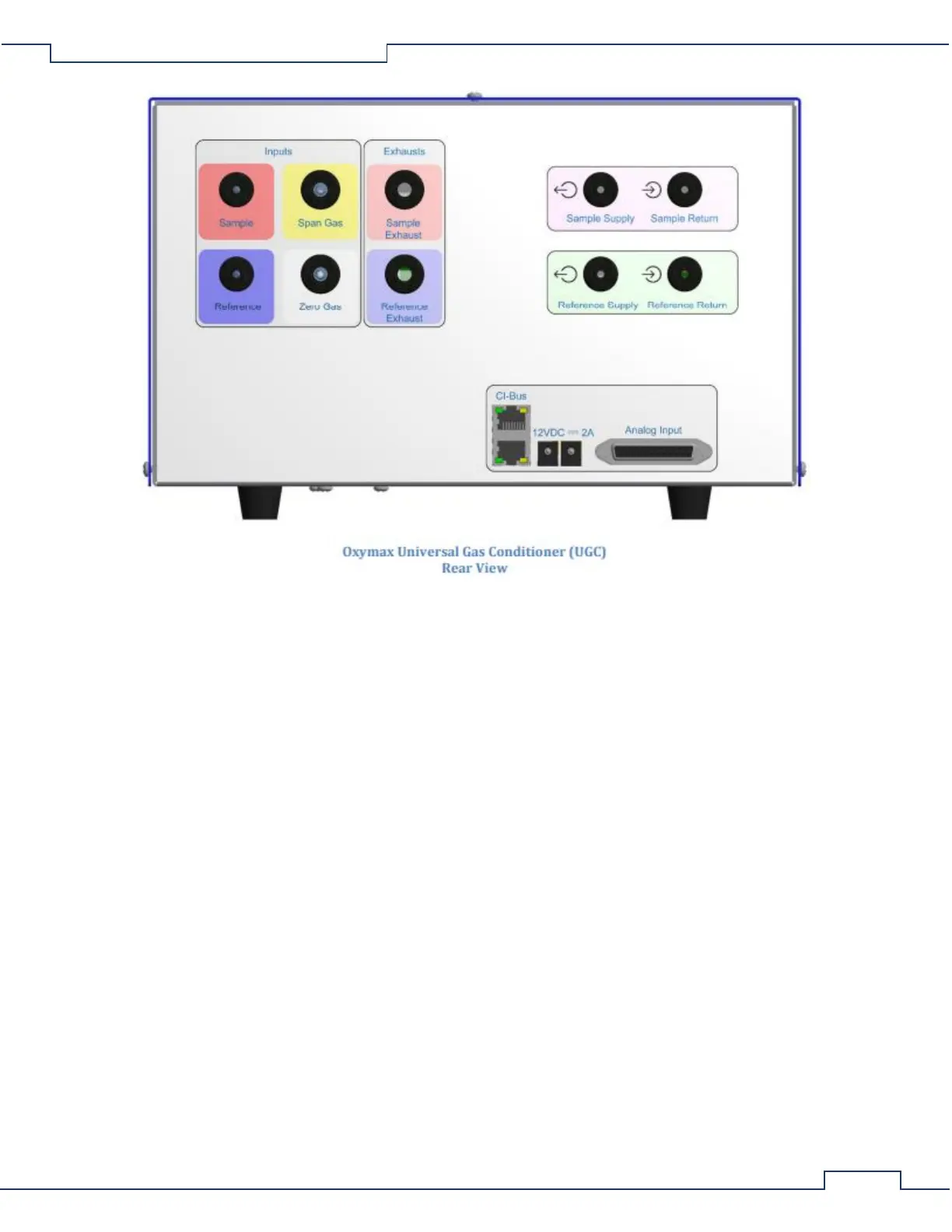
1. Sample – The input port for an ammonia-trapped and particle-filtered sample from a Universal Flow
Controller’s selected “Test Out” port.
2. Reference – The input port for a particle-filtered sample from the room air reference (typically the
same source provided to the cages).
3. Span Gas – The input port for connection from a particle filtered span gas (used for calibration of all
sensors).
4. Zero Gas – The input port for connection from a particle filtered source of CO2 free gas. Based upon
the oxygen sensor employed, this can be a column of Soda lime or nitrogen (N2) gas bottle.
5. Sample Exhaust – The output port for collection of the gas from the “Sample Return” input port.
6. Reference Exhaust – The output port for collection of the gas from the “Reference Return” input port.
7. Sample Supply – The output port for connection to the serially connected external gas sensors:
oxygen, methane, etc.
8. Sample Return – The input port for connection from the serially connected external gas sensors.
9. Reference Supply – The output port for connection to the Zirconia Oxygen Sensor’s “Reference
Supply” input port.
10. Reference Return – The input port for connection from the Zirconia Oxygen Sensor’s “Reference
Return” output port.
11. CI-Bus – Two (2) ports for connection to the CI-Bus.
12. Power – An indicator (typically green) in the top left corner which indicates connection to DC power.
13. Tx – An indicator (typically green) in the bottom left corner which indicates the host computer is
transmitting data.