Technical and instalation
manual FLOW 38 Batch Page 10 (of 49) COMAC CAL
s.r.o.
• When blending a mixture of substances, it is necessary to install the flow meter either before
the point of blending or at a sufficient distance after it (30×d min. where d is the inside diameter
of the meter in millimetres), otherwise it will result in instability of indication.
• When plastic pipeline is used or in case of metallic pipes with internal non-conductive layer,
earthing rings are needed.
• Do not install the sensor at the suction side of the pumps; this will eliminate the risk of vacuum
and possible damage to the measuring tube lining.
• Pumps, bends and elbows found closely in succession in various levels should be at a distance
of 20×d at least before the flow sensor. In case of a separate elbow or bend, the placement
10×d before the meter is recommended.
• When piston pumps, diaphragm pumps, and flexible tube pumps are used, it is necessary to
install a pulse damper in the system.
• In order to provide the highest accuracy, it is important to ensure permanent flooding for the
sensor (for example, by installation of the sensor in the U-shaped pipeline) even if the sensor
is equipped with empty tube test. This will serve as an additional safety measure for detection
of non-flooded tube.
The responsibility for suitability and adequacy of application of induction flow meters is borne by the
designer or possibly the user himself.
Actual installation in pipeline
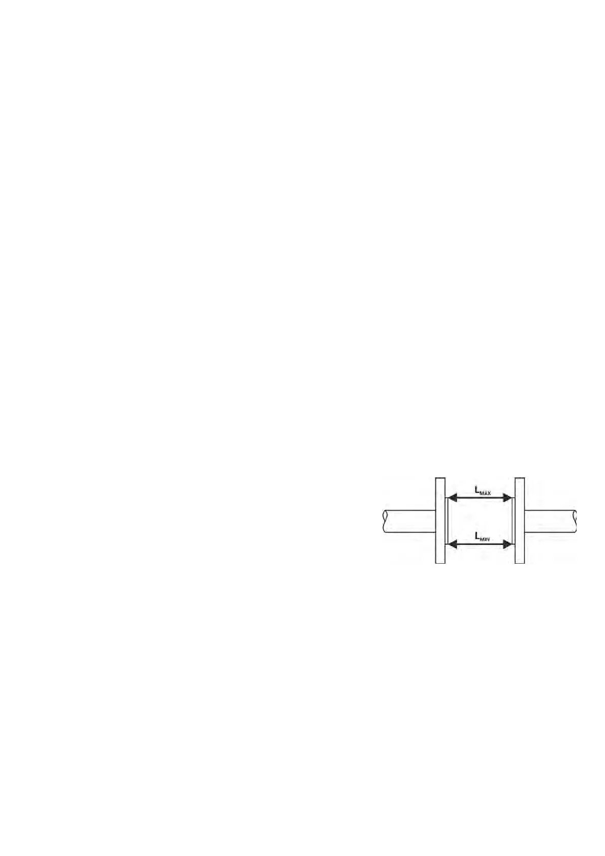
When welding both counter-flanges to the pipelines, it is
necessary to maintain their alignment so that levelness of
bearing surfaces of the flanges onto the front faces of the
detector is ensured (at the same time, this must not be achieved
by unequal tightening of the bolts as there is a risk of leakage
due to thermal loading in the future or the measuring tube may
break during such tightening). The difference of L
MAX
and L
MIN
distances of the sealing surfaces of the flanges before the flow
sensor is installed must not be greater than 0.5 mm.
The opposition of the holes in the counter-flanges for the bolts should be ensured in the same manner
and a sufficient room behind the flanges should be available for the bolts and nuts so that the actual
installation of the sensor in pipeline and its attachment with the bolts is made possible.
The manufacturer recommends using an intermediate piece during welding. It is absolutely excluded
to use the flow sensor as an intermediate piece due to thermal damage. The welding current must not
run through the flow sensor during electrical welding. The installation of the flow sensor is carried out
after welding, coating, building and similar works are completed.
The actual installation is performed by the fixation between the counter-flanges that are welded to the
calming pipeline (5×d before and 3×d in the direction of flow) whereas the liquid must run through the
flow sensor in the direction indicated by the arrow on the sensor name plate.