Technical and instalation
manual FLOW 38 Batch Page 9 (of 49) COMAC CAL s.r.o.
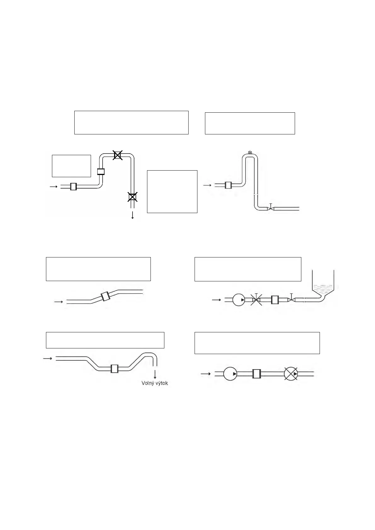
Installation examples
Trouble-free and exact operation of the meter is dependent on its correct location in the system. The
most frequent methods of the placement are shown in the following figures:
Recommended installation locations Downtake pipe
Horizontally laid pipeline Long pipeline
Free inlet or outlet Pumps
The flow of liquid flow in the flow sensor should be steady and free of whirling. For this reason,
straight sections of pipeline with the same ID as that of the flow meter before and after the flow sensor
(with permissible deviation of +5%). Recommended minimum length of straight sections is 5×d before
the flow sensor and 3×d after the flow sensor where d is the inside diameter of the meter in millimetres.
The same principles apply before and after the flow sensor in case of bi-directional flow measurement.
Recommendations
• In case of whirled up flow, extend the calming sections of pipeline or integrate a flow
conditioner.
Install an air bleed valve
after the sensor ⊗
Place the sensor in a slightly
ascending pipeline
empty;
erroneous
measurement
Install controls and shut-off
valves always after the sensor
Built in the U-shaped pipeline
The flow meter must not be installed
in the suction side of the pump
Bubbles are accumulated in the
pipeline; erroneous measurement