Technical and instalation
manual FLOW 38 Batch Page 25 (of 49) COMAC CAL
s.r.o.
electrodes are flooded. Just before the installation, the water is discharged and the sensor is installed
into piping. Right after installation, piping is filled with a medium so that the electrodes cannot dry
off.
If the meter has no electrode for empty tube detection, do not connect the meter to power before filling
the system with the fluid to be measured and power off the meter before system discharge.
Once the meter is powered up, the green LED on the front glazed panel is lit, confirming the supply
voltage on the control PCB and stabilization of parameters of the meter takes place subsequently. The
stabilization is indicated on the meter's display. After that period of time, the meter starts measuring.
Meter status
It is displayed continuously on the screen as one of the main menu items and in case of a non-standard
state or a failure, this is displayed by alternating indication of the status and main menu basic data and
the operator is warned by a text. The meter status is divided into 4 basic groups:
1) OK everything is all right
2) Warning the meter takes measurement but some of the parameters are out of range
3) Error critical error – the meter does not take measurement
4) Empty tube if the EMPTY TUBE TEST function is activated
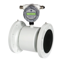
Flow direction:
The arrow indicates the direction liquid flow inside the sensor and thus the correct orientation of
the meter's sensor for installation in piping. In case of inversely performed installation, it is possible
to toggle the direction in electronics between positive/negative and thus avoid incorrect value
imaging and reading out .
Basic parameter settings
The meter or flow meter parameters are set by the manufacturer in accordance with the purchase order.
If these values are not indicated in your purchase order, the meter will be set up using the default
parameters in accordance with the meter's range. The operator can make modifications by means of
three buttons on the meter's panel or through the RS485 interface.
Safety rules for operator
Any interventions in the inductive flow sensor and evaluation unit itself are illegal on the part of
operator and they may lead to direct scalding by medium. Perform electrical connection always after
powering off.
Flow 38 Batch operating instructions
The meter is provided with two external buttons on the side of the electronics housing and with three
internal buttons on the bottom of the measuring electronics PCB which is accessible after unscrewing
the front glazed cover.
Functions of control (lower) buttons: