Home
COMAC CAL
Measuring Instruments
FLOW 38
COMAC CAL FLOW 38 Installation And Technical Manual
4
of 1
of 1 rating
49 pages
Give review
Manual
Specs
To Next Page
To Next Page
To Previous Page
To Previous Page
Loading...
Technical and instalation
manual
FLO
W 38 Ba
tch
Page
13
(
of
49
)
COMA
C CAL
s.r.o.
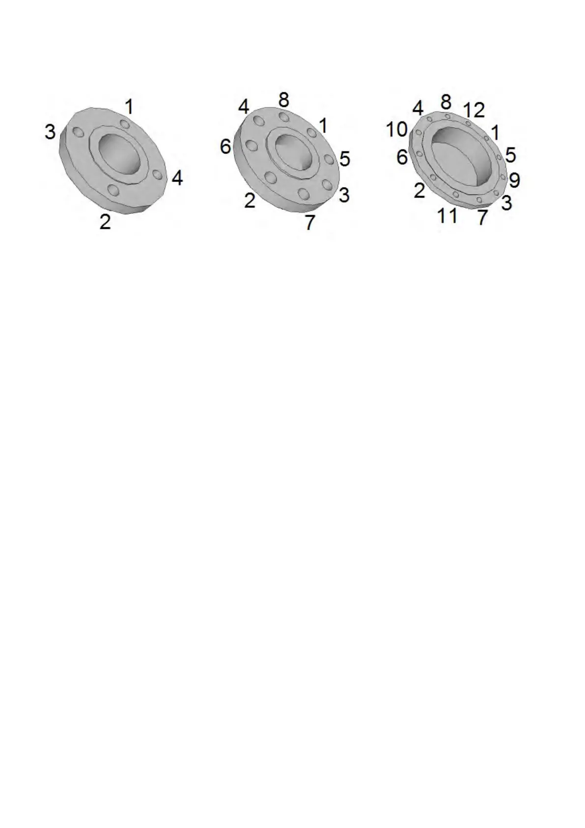
If the bolts are tightened too much during the
installation of pipework components, deformation of th
e
sealing surface may occur. In consequence, the torque values
indic
ated
in the t
able ar
e used
as a
guidance for tightening the screws and bolts.
12
14
Table of Contents
Table of Contents
2
Content
2
Description of Device
5
Scope of Delivery
5
Storage Conditions
6
Warranty
6
Installation in Pipeline
7
Important Information for Selection of Location
7
Outdoor Conditions
7
Sources of Disturbances
7
Vibration
7
Actual Location
7
Installation Examples
9
Recommendations
9
Actual Installation in Pipeline
10
Installation Position
11
Measurement Error Caused by Incorrect Mounting Installation
11
Installation in Piping and Placement of Measuring Electrodes in Flow Sensor
12
Tightening Torques
12
Seal
16
Earthing
16
Earthing Rings
17
Electrodes
17
PTFE, PFA and ETFE Lining
17
High Temperature Pipeline and High Temperature Medium
18
Installation Check
18
Wiring
18
Important Information
19
Flow Sensor Connecting Cable
19
Evaluation Unit
19
Installation of the Meter's Detached Evaluation Unit
20
Wall Mounting
20
Meter Wiring of Batching Unit
21
Electrical Connection of the Meter
22
Impulse Output
22
Buttons START, STOP
23
Technical and Instalation Manual FLOW 38 Batch
23
Controlling of the Batching Valve
23
Data Output
23
Protection Degree
23
Replacement of Tube Fuse in the Meter
23
Wiring Check
24
Putting into Operation
24
Meter Status
25
Basic Parameter Settings
25
Safety Rules for Operator
25
Flow 38 Batch Operating Instructions
25
Functions of Control (Lower) Buttons
25
Function of Setting Buttons ( under Display)
26
Basic Display Menu Contains the Following Items
27
Meter Settings Via the Display
27
Flow Meter Settings
28
Date and Time
29
Operation Time Counter
29
Power Loss Counter
29
OUT1 Setting
30
Impulse Output
30
Flow Switch Operation
30
Settings of Dose Range
32
Communication
32
Idle State Basic Indications on Display
33
Flow Rate Damping
33
Display Backlight
33
Serial Number
34
Calibration Constants
34
Empty Tube Test
34
Firmware Version
34
Dead Band - Measurement of Start Suppression
35
Zero Calibration
35
Flow Simulation
35
Language
36
Counter Resetting
36
Nominal Diameter (DN)
36
Flow Direction
36
Signal Saturation Filter
37
Flow Units Displayed [Q]
37
Volume Units Displayed [V]
37
User Counter with Reset Option
38
Password Change
38
Default Settings (Original Factory Settings)
38
Technical Data
39
Factory Settings
41
Basic Sensor Sizes
43
Threaded Design
43
Sandwich (Inter-Flanged) Design
44
Flanged Design
45
Food Industry Design
46
Nomogram for Quick Proposal of the Measured Place
47
Reduction in DN Pipe
47
Faults and Their Symptoms During Measurement
48
Flow Sensor Cleaning
48
Servicing
48
Form for Shipment of the Meter Back to COMAC CAL S.r.o
49
Other manuals for COMAC CAL FLOW 38
Installation And Technical Conditions
54 pages
4
Based on 1 rating
Ask a question
Give review
Questions and Answers:
Need help?
Do you have a question about the COMAC CAL FLOW 38 and is the answer not in the manual?
Ask a question
COMAC CAL FLOW 38 Specifications
General
Brand
COMAC CAL
Model
FLOW 38
Category
Measuring Instruments
Language
English